INSTRUCTION MANUAL
HWS 3000G
TDK-Lambda
<Page>
HWS 3000G - 24 /□
7/49
Option(*1)
Rated output voltage
Series name
Output power type
Series name
(*1)
Blank : Standard
/HD : Refer to the specifications for details
・With coating on both sides of PCB
・Designed to meet 「MIL-STD-810G」
(Vibration・Shock)
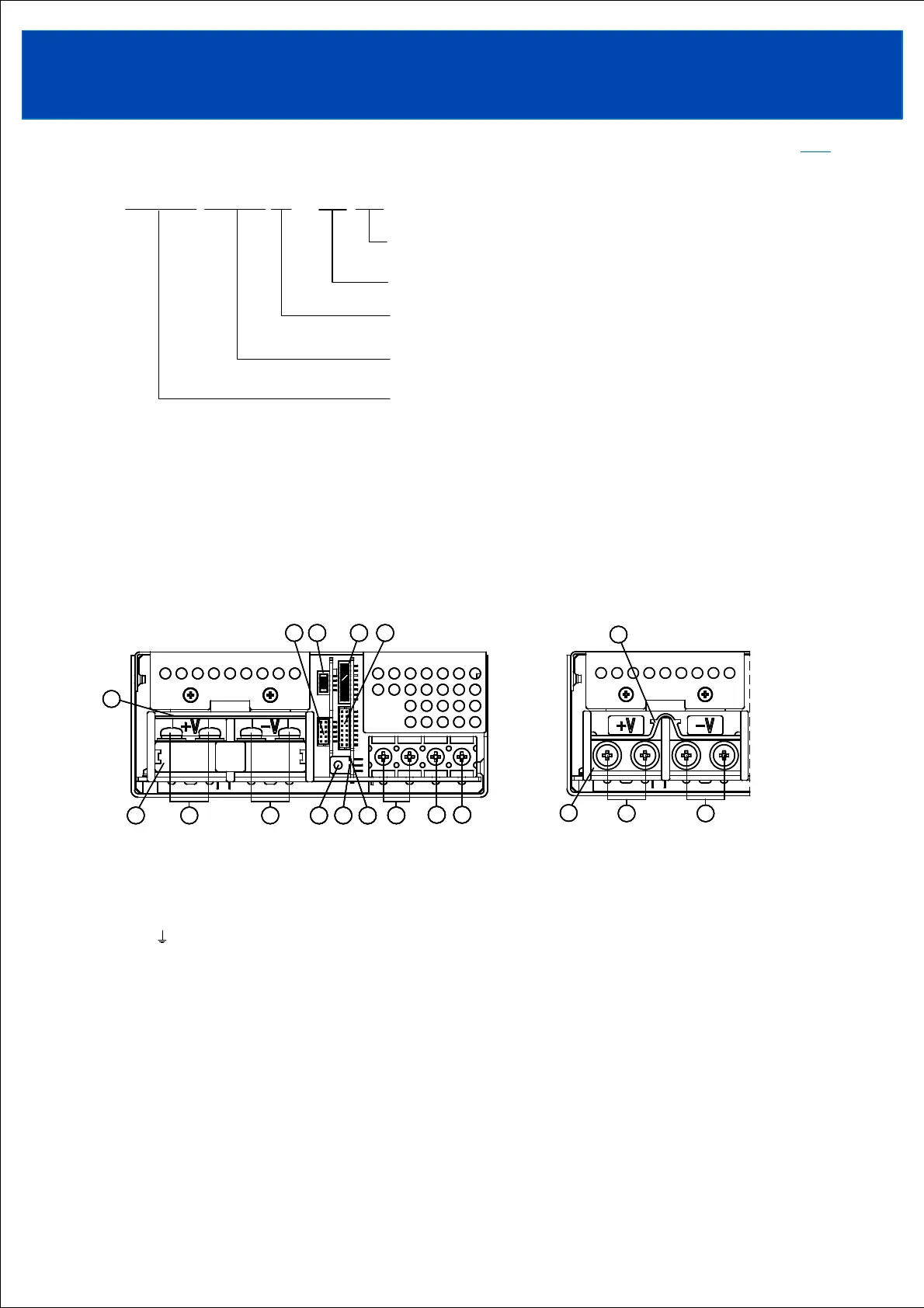
Top side screw (Shipment condition)
① N : Input terminal Neutral line (Fuse in line) (M4 screw) *Basic insulation between FG
② L : Input terminal Live line (Fuse in line) (M4 screw) *Basic insulation between FG
③ : Earth terminal (FG) (M4 screw) *Connected to the power supply case inside the power supply
④ -V : -Output terminal (62.5A max. / terminal, M5 screw) *Basic insulation between FG
⑤ +V : +Output terminal (62.5A max. / terminal, M5 screw) *Basic insulation between FG
⑥ Output voltage adjustment trimmer
⑦ Output monitoring indicator (Green LED lights up when power is output)
(Flashes when output voltage is 60V or more after input voltage cutoff)
⑧ Communication display LED (yellow LED flashes during communication)
⑨ Terminal cover 1
⑩ Terminal cover 2
⑪ Signal connector CN41 *Functional insulation between FG
⑫ Signal connector CN42 *Functional insulation between FG
⑬ Signal connector CN61 *Basic insulation between FG
⑭ Signal connector CN71 *Functional insulation between FG
2
44
11
33
1
3
55 7788 78
99
6661010
1111 121213131414
2
4
1
3
5 78
9
610
11 121314
4455
1010
99
45
10
9
Front side screw
TOPTOP
1. Model name identification method
2. Terminal explanation