INSTRUCTION MANUAL
HWS 3000G
TDK-Lambda
<Page>
8/49
CN42
CN41
1
2
3
4
5
6
7
8
9
10
11
12
13
14
15
16
1
2
3
4
5
6
7
8
9
10
11
12
13
14
15
16
1
2
3
4
5
6
7
8
9
10
11
12
13
14
15
16
1
2
3
4
5
6
7
8
9
10
11
12
13
14
15
16
TOPTOP
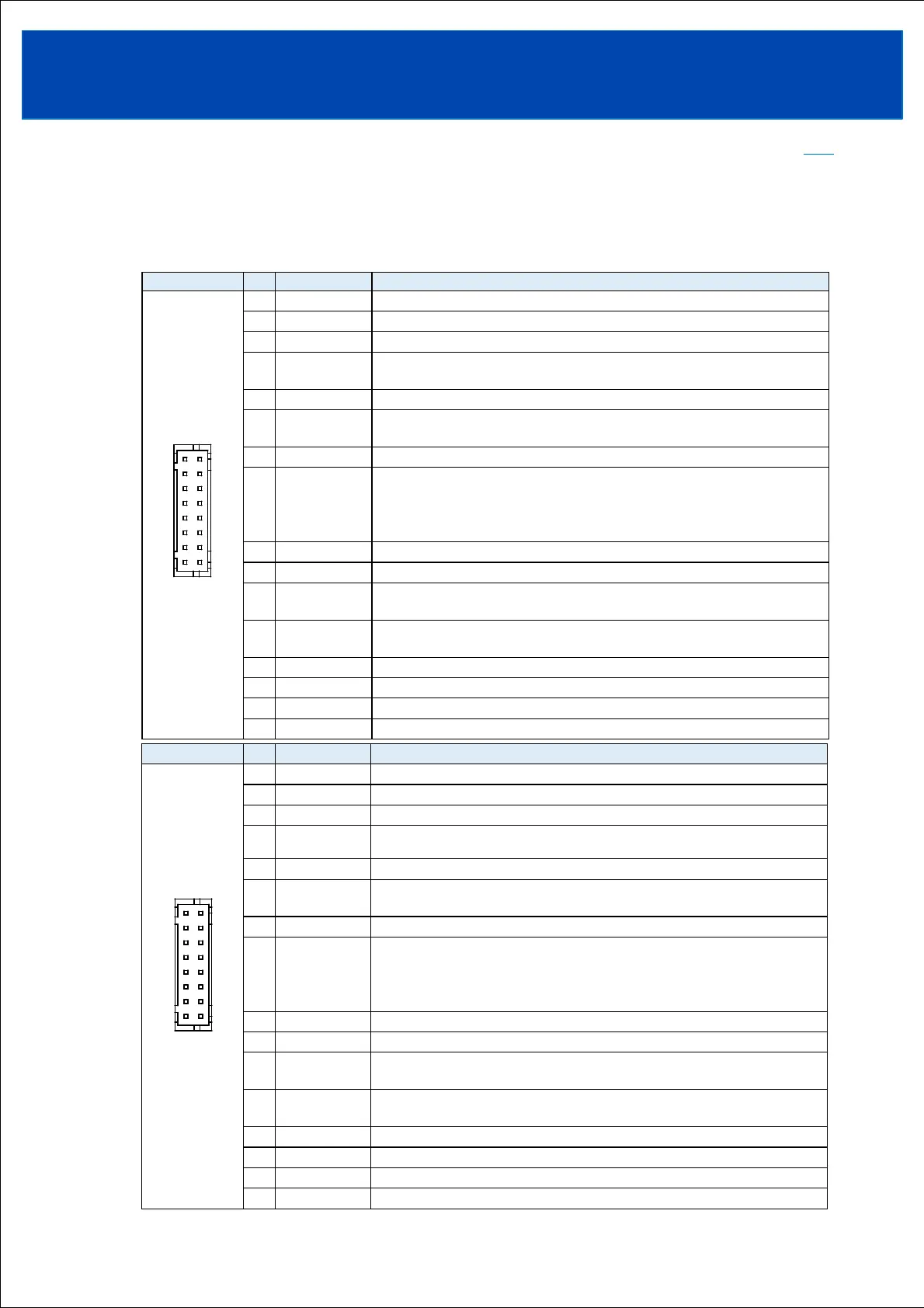
2-1. Connector pin Configuration and Function
2-1-1. CN41、CN42
Terminals with the same name, CN41 and CN42, are connected inside the power supply.
If you short the terminals on the CN41 side, the terminals on the CN42 side will also short.
*Please note that pin No. 5 has different functions between CN41 and CN42.
CN41 and CN42 are isolated from the power input and output circuits.
Configuration No. Pin name Function
1 -D
Differential data - for RS-485
Differential data + for RS-485
Termination resistor terminal for RS-485
Ground for -D,+D,A/I,HL
(internally connected to AG terminal.)
Address assignment input terminal
Ground for -D,+D,A/I,HL
(internally connected to AG terminal.)
Redundant operation invalid terminal
External power supply terminal for communication
By applying the communication power supply voltage externally, settings and
operation history can be read through communication without applying an AC input
voltage.
Remote ON/OFF control terminal
Remote ON/OFF control terminal
Ground for CB,VB,CC,CV
(internally connected to DG terminal.)
Ground for CB,VB,CC,CV
(internally connected to DG terminal.)
Current balance terminal. (For current balancing in parallel operation.)
Voltage balance terminal (For voltage balancing in series operation)
Output current external control terminal.
Output voltage external control terminal.
Configuration No. Pin name Function
1 -D
Differential data - for RS-485
Differential data + for RS-485
Termination resistor terminal for RS-485
Ground for -D,+D,A/O,HL
(internally connected to AG terminal.)
Address assignment output terminal
Ground for -D,+D,A/O,HL
(internally connected to AG terminal.)
Redundant operation invalid terminal
External power supply terminal for communication
By applying the communication power supply voltage externally, settings and
operation history can be read through communication without applying an AC input
voltage.
Remote ON/OFF control terminal
Remote ON/OFF control terminal
Ground for CB,VB,CC,CV
(internally connected to DG terminal.)
Ground for CB,VB,CC,CV
(internally connected to DG terminal.)
Current balance terminal. (For current balancing in parallel operation.)
Voltage balance terminal (For voltage balancing in series operation)
Output current external control terminal.
Output voltage external control terminal.