18Technetix Group LimitedRev.1.0.1_0217
4. Ensure that all RF output ports in use are connected to a 75Ω terminated load to prevent reflections aecting
the RF spectrum analyser readings for commissioning levels. Connect a spectrum analyser to the -20 dB Output
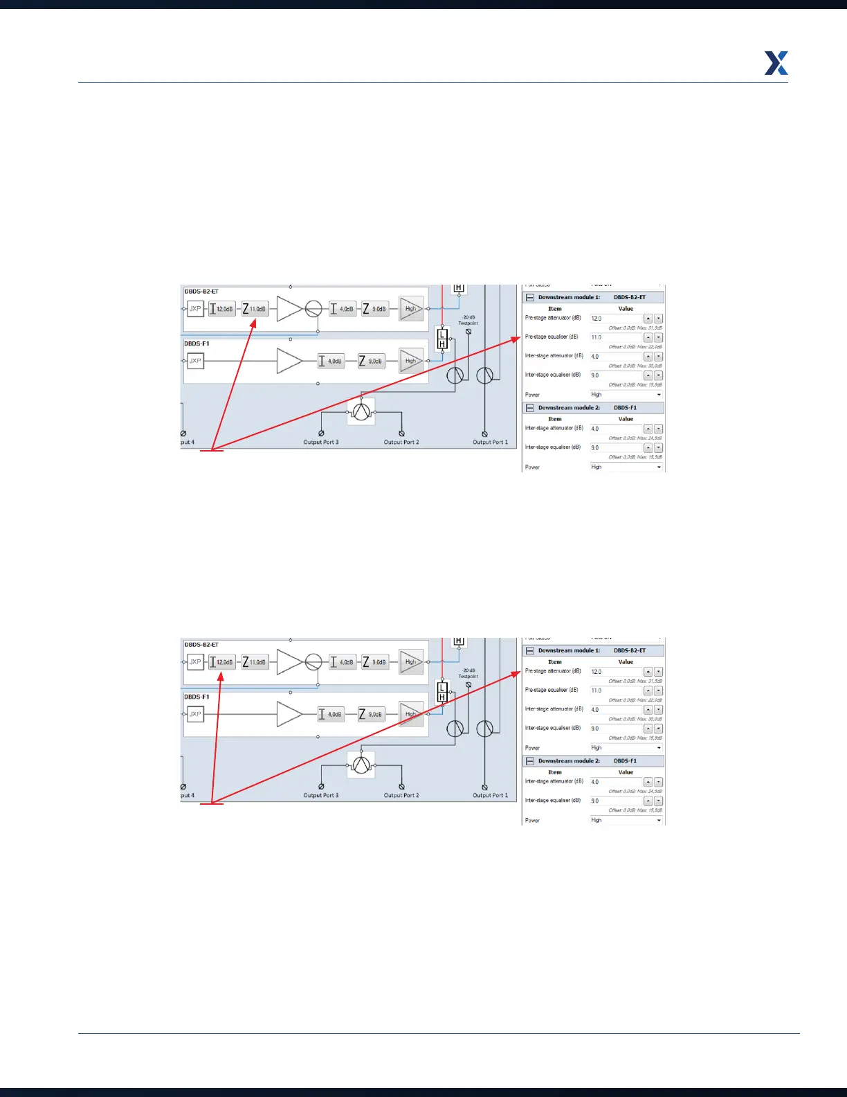
test point. Read the pilot frequency levels and set them to the network design/system levels required by adjusting
the pre-stage equaliser first to obtain the correct pilot tilt/slope value as required in the network/system design
documentation. Remember, once a value is set in the Pre-stage equaliser field, the amplifier schematic, or the
parameter view table to the right of the application screen, click on Send to amp to set these values electronically.
Then check the tilt/slope between the pilot frequencies on the spectrum.
Pre-stage
Equaliser (dB)
Pre-stage
Attenuator (dB)
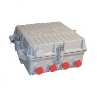
5. Next set the pilot frequencies’ levels to the network/system design levels by changing the Pre-stage attenuator
values in the amplifier tab schematic or parameter view table. Remember to click on Send to amp after changing
the values in the BLL application and check that the levels are correct on the RF spectrum analyser.