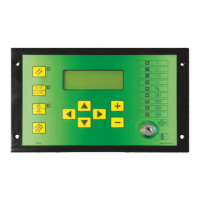
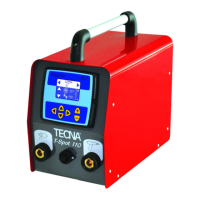
Instruction Manual ITEM TE700 TECNA S.p.A.
78/128
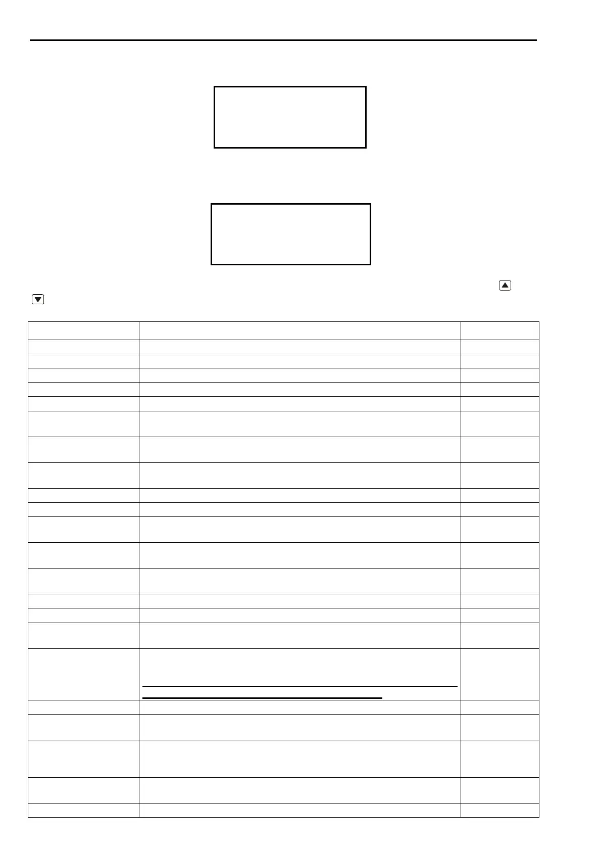
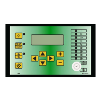
2.16 – CHECK INPUT – DIAGNOSTIC INVERTER
-TE700 VER. 1.09--
PROGRAM COPY
DIAGNOSTIC TE700
>DIAGNOSTIC INV.
This menu displays the status of the inputs and outputs of the inverter unit connected to the
TE700. It is used to check the working efficiency of the inverter unit.
DIAGNOSTIC INV.
>VERSION INV. 2.02
RIC 1 OFF
RIC 2 OFF
The following inputs are mentioned in the list which may be scrolled by means of the
and
keys.
PARAMETER PARAMETER DESCRIPTION VALUE
VERSION INV. It indicates the software version installed in the inverter. X.XX
RIC 1 It indicates the status of the signal relative to RIC 1 inside the inverter. ON – OFF
RIC 2 It indicates the status of the signal relative to RIC 2 inside the inverter. ON – OFF
RIC 3 It indicates the status of the signal relative to RIC 3 inside the inverter. ON – OFF
RIC 4 It indicates the status of the signal relative to RIC 4 inside the inverter. ON – OFF
TERM It indicates the status of the signal relative to thermostat wired on the
inverter.
ON – OFF
DRIVER It indicates a power semiconductor driver fault. NO ERR –
ERR
EMERGENCY It indicates the status of the signal relevant to the emergency chain on
the inverter.
ON – OFF
WELD NO WELD It indicates the status of the weld-no weld signal inside the inverter. ON – OFF
TRIGGER It indicates the status of the welding start signal inside the inverter. ON – OFF
RIC 5 / WELD 2 It indicates the status of signal RIC 5 or SEAM WELD. 2 inside the
inverter.
ON – OFF
OUT EV WATER It indicates the status of the inverter output that controls the EV for the
cooling circuit water.
ON – OFF
OUT READY It indicates the status of inverter output for the READY signal
transmitted to the TE700 control unit.
ON – OFF
OUT LOCK It indicates the status of the LOCK output of the inverter. ON – OFF
OUT WRONG It indicates the status of the WRONG output of the inverter. ON – OFF
VER. DRIVER It indicates the software version installed inside the board that checks
for the capacitors' charged condition.
XX.X
CAPACITOR VOLT It indicates the voltage present on the bank of capacitors inside the
inverter.
Warning: this measurement is indicative and should not be used
as a reference when operating in the inverter unit.
000V
BOARD TEMP. It indicates the room temperature on the inverter unit. XX.X°C
SINK TEMP. It indicates the temperature of the dissipater on which the power
semiconductors are installed.
XX.X°C
THERMAL LEVEL It indicates the use percentage of the inverter in case the thermal limit
switches tripped relative to the primary of the weld transformer and/or
the diodes of the secondary rectifier.
XXX%
SCR DRV STATUS Alphanumeric code that indicates the operating status of the board
that checks for the capacitors' charged condition.
XX
INV. SERIAL Inverter unit serial number. XXXXX