F
IGURE
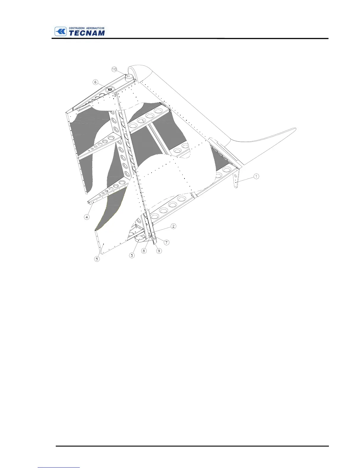
C-9
F
IN AND RUDDER
Rudder mass balancing (10) is placed on the rudder upper rib’s horn. To inspect
this part it is necessary to remove the composite tip.
To remove the rudder, disconnect the control cables from the bellcrank, loose
and remove the upper bolt (e.g. removing the composite rudder tip) and remove
moving upwards the rudder.
Control system layout (fig. C-10) is a steel cable driven and circuit terminates
on rudder pedals and then on the nose wheel steering lever.
Rudder pedals (1) are attached to two pushrods (3) that transmit steering motion
to the nose gear leg through a lever. This lever hinges on the engine mount and
springs connected to the steering lever via two small plates allow for a more ef-
fective realignment of the rudder. Length of pushrods can be modified via adjust-
able ball and socket connections.
Cable tension must be checked periodically and adjusted to proper value using
the turnbuckles (Tension = 20 daN ± 2). Pulley (5) condition and their smooth