English
4
BLAST CHILLER ISTRUCTION C-2003 06/2011
2
.6 REFRIGERATION COMPONENT CONNECTIONS
REMOTE ASSEMBLIES
Appliance power lines are sized for installation distances of
up to 10 metres. For greater distances, seek advice from.
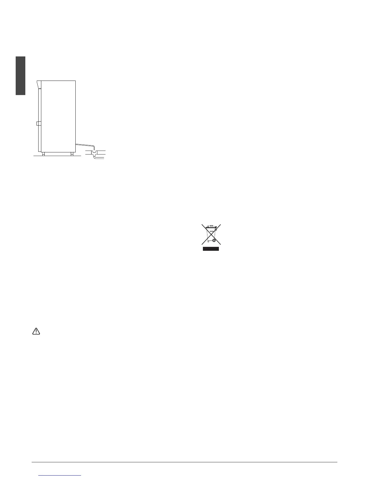
2.7 CONDENSATE DRAINAGE CONNECTION MOD.
t
Fit a condensate/wash water drainage hose with a minimum
diameter of 1” (“Geberit” or similar type).
Provide a waste pipe with a
trap with a diameter of at least 1
1/2” at floor level.
2.8 INFORMATION FOR THE INSTALLATION TECHNICIAN
Before starting up the machine, check that it has been cor-
rectly installed and commissioned (test report).
1. Check that there are no gas leaks from weldings or joints
made during installation works.
2. Check that the pipes connecting the condenser to the re-
mote condensing unit have been well insulated.
3. Check all wiring connections.
4. Check electrical input.
5. Check the standard pressure in the refrigerant system.
6. Check the water connections and efficiency of the pressure
switch valve during operation, as well as the flow of con-
densing water (in water-cooled units).
7. Perform at least one blast freezing cycle (to the SET tempe-
rature) and one manual defrosting cycle.
In the event that the appliance or the remote condensing
unit have not been transported in a vertical position (e.g. on
the back) or have been overturned during installation works,
allow at least 4 hours before starting up the equipment.
• Inform the customer of the exact purpose of the appliance,
with specific reference to the use and requirements of the
customer.
The appliance must be installed and put into service by a
technician authorised.
2
.9 SAFETY AND CONTROL SYSTEMS
• Door microswitch:
shuts down fan operation in the cell when the door is ope-
ned.
• General fuses:
p
rotect the power circuit against short circuiting and over-
loads.
• Compressor heat relay:
intervenes in the event of overloads or operating faults.
• Safety pressure switch:
i
ntervenes in the event of excessive pressure in the refrige-
rant circuit.
• Plug fuses:
intervene in the event of overpressure or operating fault in
the safety pressure switch (see above).
• Chamber temperature control:
operated by the electronic board by means of a probe inside
the cell.
• Temperature control end defrost cycle:
controlled by the electronic board by means of the probe in
the evaporator.
2.10 DISPOSAL OF WASTE ELECTRONIC AND ELECTRICAL
EQUIPMENT WEEE (only Mod.
w
)
Fulfilling Directives 2002/95/CE, 2002/96/CE and
2003/108/CE on the disposal of waste electronic and elec-
trical equipment.
The crossed out wheeled bin symbol indicates the
product must be collected separately from other
waste when it has become redundant. Differentia-
ted collection of this equipment is arranged and
handled by themanufacturer.
Consequently, the user who is wanting to dispose of this
equipment must contact the manufacturer and follow the
method the latter has adopted to allow separate collection
of the redundant equipment.
Appropriate differentiated collection for the subsequent re-
cycling, treatment and eco-friendly disposal of the disman-
tled equipment prevents possible negative effects on the
environment and health and facilitates the recycling of ma-
terials used in manufacturing the equipment.
Administrative sanctions foreseen by the regulations in force
shall be applied for any abusive disposal of the product by
the holder.