2-14
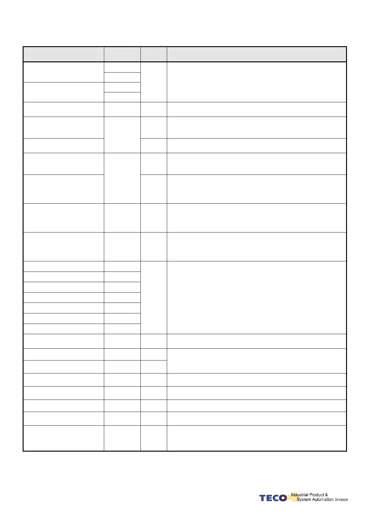
Explanation of General I/O Signal Function
Signal Name
Function
Symbol
Mode I/O Operation and Function
Pulse
Position Pulse Command
Input
/Pulse
Sign
Position Sign Command
Input
/Sign
Pe
The Driver can receive 3 kinds of Command below:
. (Pulse)+ (Sign)
. (CCW)/ (CW)Pulse
.AB Phase pulse
Open Collect Position
Command PW Input
OPC
Pe
When open collect input in position command, OPC and IP24
can be close, and using internal 24V power and resistor.
Speed Analog command
Input
S
In Speed Mode, when external speed command is operated at
SPD1=0, SPD2=0, input the voltage range: -10V~+10V, Sn216
can be set input voltage: ±10V’s Motor output speed.
Torque Analog Command
Input
SIC
T
In Torque Mode, input the voltage range -10~+10V, Tn103 can
be set input voltage ±10V’s motor output torque.
Torque Control Speed Limit
Command
T
In Torque Mode, when external speed limit is operated at input
connect point SPD1=0 & SDP2=0(P.S), input voltage range:
0~+10V, 10V’s speed limit stands for motor’s ratio speed.
CCW Torque Limit
Command
TIC
S
In Speed Mode, when external torque limit is be used at input
connect point TLMT=1(P.S.) , input voltage range: 0~+10V, to
input 10V will limit the motor CCW torque having 300% of ratio
torque.
Analog Monitor Output 1
MON1
ALL
Operating the motor to control the current speed to transform
the voltage output in accordance with the rate (±10V/1.5 times
ratio speed) CCW stands for positive voltage, CW negative
voltage.
Analog Monitor Output 2
MON2
ALL
Operating the motor to control the current torque to transform
the voltage output in accordance with the rate (±10V/3.5 times
ratio torque) CCW torque stands for positive voltage, CW
negative voltage.
Encoder Output A Phase
PA
Encoder Output / A Phase
/PA
Encoder Output B Phase
PB
Encoder Output / B Phase
/PB
Encoder Output Z Phase
PZ
Encoder Output / Z Phase
/PZ
Home Signal Output
ZO
ALL
Outputting the Motor Encoder Signal through pulse per rotation
handle. The pulse quantity of every rotating can be set in
Cn005.
When “1” is set in Cn004, it is CCW rotation from the motor load
terminal direction, and A Phase gets 90 degree ahead B Phase.
Signal Output is Line Driver.
Analog Signal Ground
Terminal
AG
ALL
Analog signal grounding: CN1 - > Pin 28、29、32.
+15V PW Output Terminal
+15V
ALL
-15V PW Output Terminal
-15V
ALL
To provide ±15V output power (Max. 10mA), which can be used
in servo drive – external voltage command. Suggestion: Using
the variable resistance which is more than 3kΩ.
DI PW Common Terminal
DICOM
ALL
Digital input power supply common terminal.
DO PW Common Terminal
DOCOM
ALL
Digital output power supply common terminal.
+24V PW Output
IP24
ALL +24V power output terminal (Max. 0.2A).
+24V PW Ground Terminal
IG24
ALL +24V power grounding terminal
Power supply for absolute
encoder
BAT+
ALL
Power supply for absolute encoder. If user had not battery
module, user can use this pin to supply power to absolute
encoder. The range of power supply is 3.3V~3.65V.
P. S .: “1” stands for “close loop with IG24”; “0” stands for “open loop with IG24”.
PW is abbreviation of Power