2-15
(b) Digital I/O Signal:
For many kinds of application, the digital input/output terminal layout of all operation mode are accordingly
different. In order to provide more functions, our drives can provide multi terminal layout settings. Users can set these
functions for application.
Digital input terminal layout provides 13 (Pin1~13) programmable terminal; digital output terminal provides 4
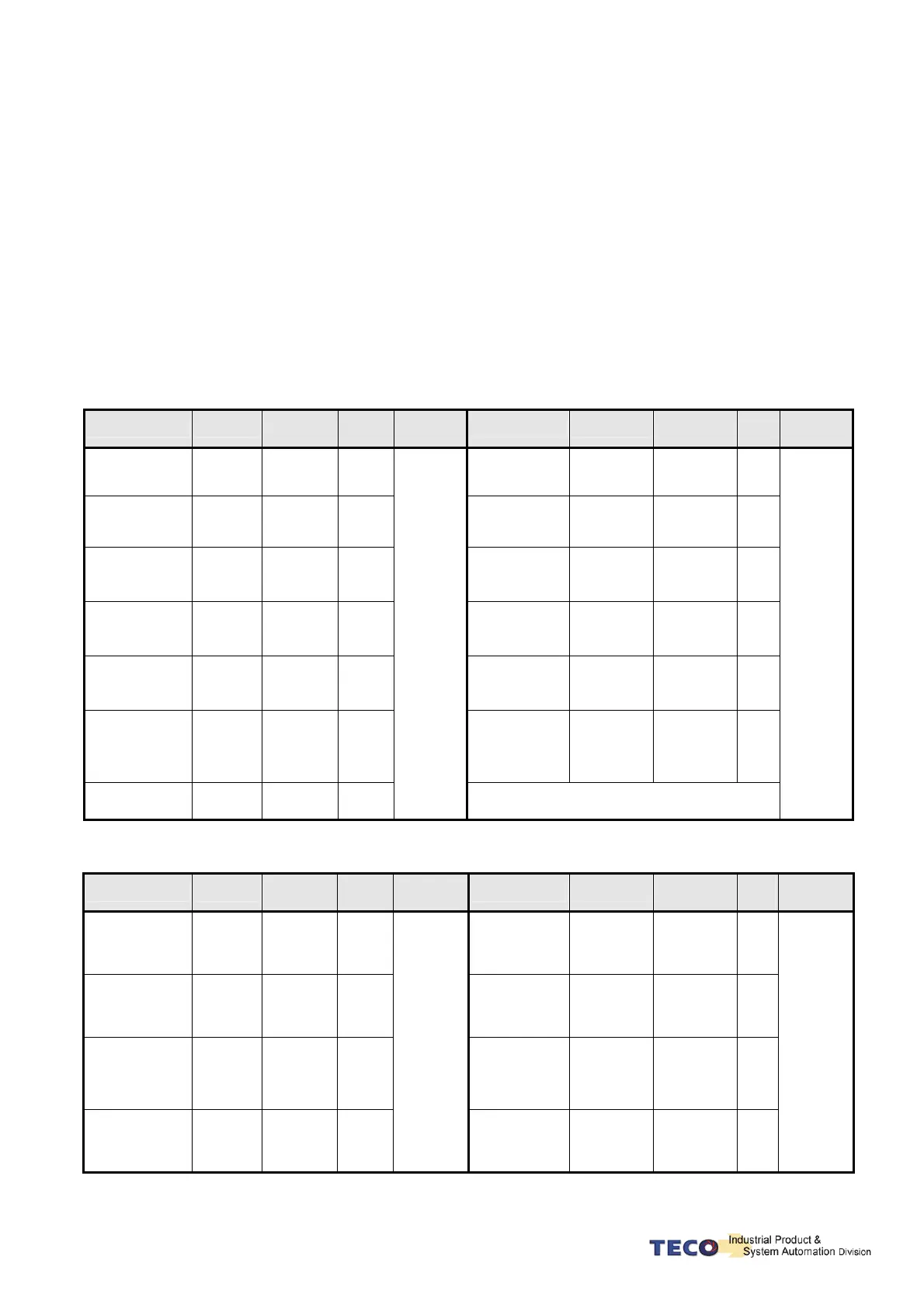
(Pin18~21) programmable terminals. The diagram below shows the default digital input/output terminal placement
and functions. Please refer to 5-6-1 to check related parameters setting.
Default Digital Input Terminal placement Functions and Wired Mode
Signal terminal
Function
Sign
Pin
No.
Wired
Mode
Signal terminal
Function
Sign
Pin
No.
Wired
Mode
Servo ON DI-1
SON
1 Servo Lock DI-8
LOK
8
Alarm reset DI-2
ALRS
2
Emergency
Stop
DI-9
EMC
9
PI/P Switch DI-3
PCNT
3
Internal speed
command /
Limit select 1
DI-10
SPD1
10
CCW
Operation
Limit
DI-4
CCWL
4
Internal speed
command /
Limit select 2
DI-11
SPD2
11
CW
Operation
Limit
DI-5
CWL
5
Control Mode
Switch
DI-12
MDC
12
External
Torque Limit
DI-6
TLMT
6
Reverse
Direction
Speed
Command
DI-13
SPDINV
13
Pulse error
amount delete
DI-7
CLR
7
IO1
―
IO1
Default Digital Input Terminal Layout Functions and Wired Mode
Signal terminal
Function
Sign
Pin
No.
Wired
Mode
Signal terminal
Function
Sign
Pin
No.
Wired
Mode
Servo ready DO-1
RDY
18
Torque limit/
Alarm code
A0
DO-5
LM/A0
22
Alarm DO-2
ALM
19
P action /
Alarm code
A1
DO-6
PC/A1
23
Zero speed DO-3
ZS
20
Operation
limit/
Alarm code
A2
DO-7
ST/A2
24
Fix position DO-4
INP
21
IO2
Base Block/
Alarm code
A3
DO-8
BB/A3
25
IO2