4.3. Storage
The Mistral must be stored at vibration-less, dry and as dust free a place as possible. It may not be stored
outside of closed areas.
The air temperature must be in a temperature range between + 5 °C and + 35 °C.
The relative air humidity may not amount to any more than 65 %. The condensation of air humidity on the
surface of the Mistral must absolutely be avoided.
5. Start-up of the Mistral
5.1. Connection of an external control
The Mistral is switched on and/or headed either at the transparency keyboard or by an external/remote
control (e.g. the machine which can be exhausted). With the manual switching on, push ON/OFF key about
0,5 sec.
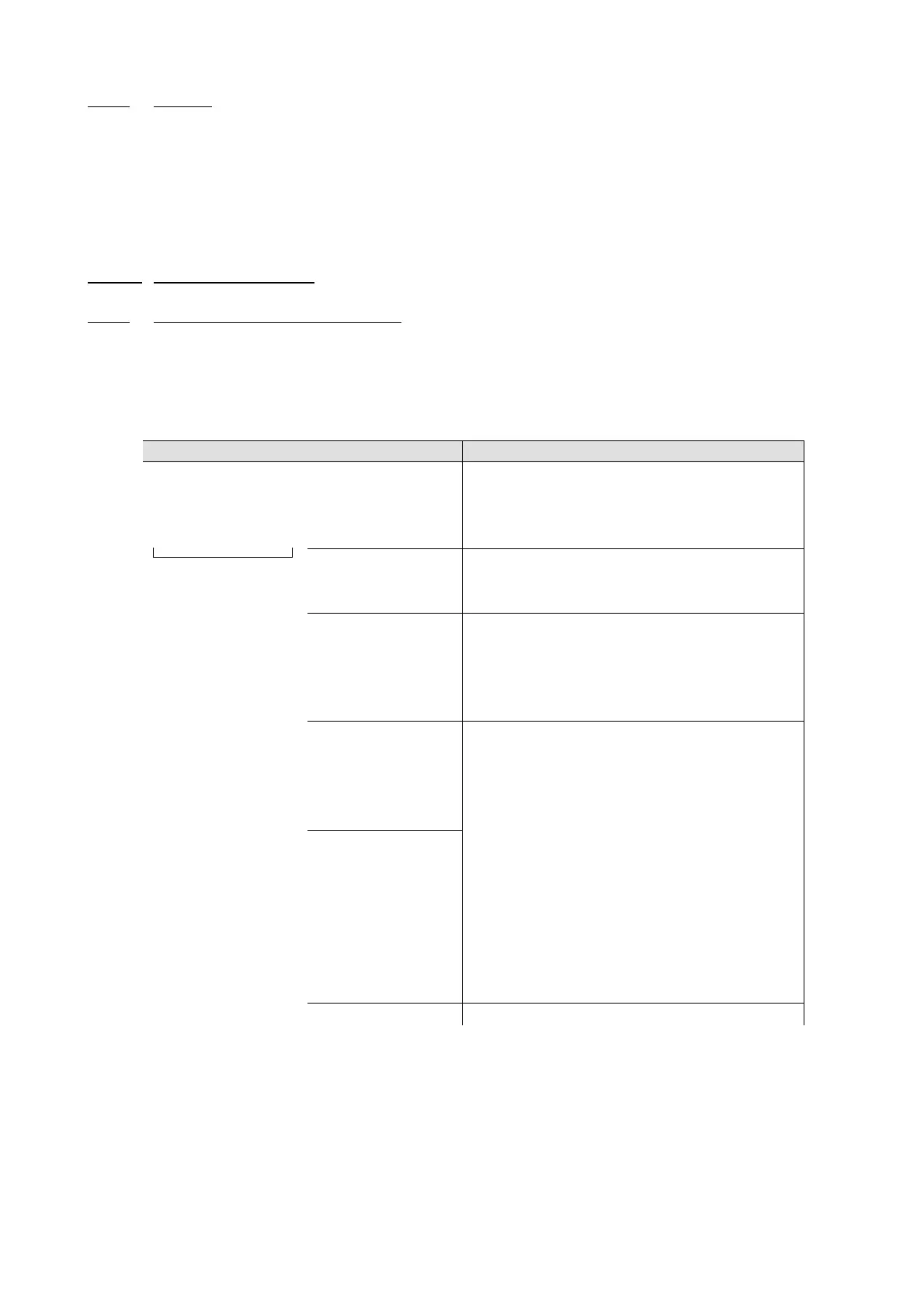
At the Mistral the connection of the remote control is made by a nine-pole cable with Sub-D9-plugs.
Illustration Pin Designation Declaration
Connector
Sub-D9, device sided
1 Start-/stop
contact
24 V DC
Input signal for starting/stop contact from the
external machine:
High: start contact (24 V DC)
Low: stop contact (0 V DC)
2 Operational
status
indicator
Output signal for operation of the filter unit:
High: Filter unit is in operation (24 V DC)
Low: Filter unit is out of operation (0 V DC)
3 „Filter full“ Output signal for failure alarm of the filter-unit:
High: Filter, activated carbon and /or brushes
are correct (24 V DC)
Low: Filters, activated carbon and /or
brushes must be changed (0 V DC)
4 Increase
capacity of
the turbine
Input signal of the external machine for
increasing the capacity of the turbine:
High: Capacity of the turbine rises (24 V DC)
Low: Capacity of the turbine remains
constant (0 V DC)
5 Reduction
capacity of
the turbine
Input signal of the external machine for lowering
the capacity of the turbine:
High: Capacity of the turbine decreases
(24 V DC)
Low: Capacity of the turbine remains
constant (0 V DC).
6 5 V DC Output signal with permanently 24 V DC
7,8 Not occupied
9
Common masse for PIN 1 to PIN 6
Schedule 1: Connection of an external control (arrangement of plug contact / connection allocation)
Operating Instructions Mistral (Plus), Mistral Eco (Plus), Mistral Super Plus 110 and 230V vers. 4.10 Page 21 of 47