VOT1; Rev 1.5; EN; 5.11.2015
TKT66 – Installation and maintenance
this case the External fault LED will be lit and the external error alarm relay will operate. In working
luminaire circuits, the LEDs are lit evenly.
More information about testing the luminaires, see Chapter 4.10 Control Module panel test functions and
alarms.
NOTE: In parallel connection the current values are multiplied by the number of the parallel connected
circuits. 700 W = 2x or 1400 W = 4x.
4.6 Operation of the central battery unit
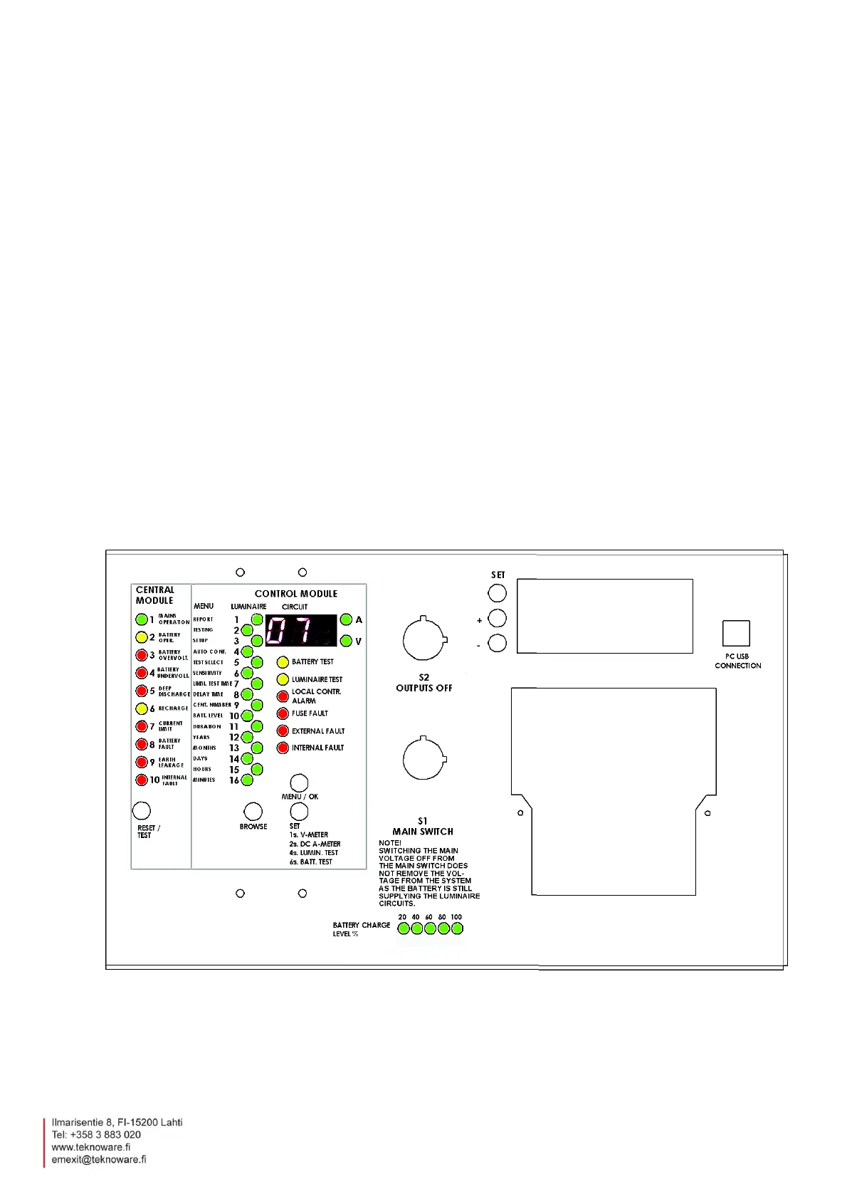
The functions are accessed by the menu structure. The green LEDs on the LED column show the basic
menu option and the number display shows the sub-options or values of it.
The menu functions of LEDs 1 and 2 are so-called basic functions. All other functions are related to the
settings of the central battery unit. The latter do not need to be changed in normal use. When the menu
functions are used, the central battery unit returns to normal mode if no functions are used for two
minutes. All functions can also be done via Bus interface using centralised management software.
4.7 Normal Status
In normal status the number display rotates the information of all circuits connected to the central
battery unit. In addressable monitoring the display will show the number of the circuit and the LED
corresponding to a luminaire will be lit. In circuit monitoring, the LEDs numbered from 16 to 1 will be lit;
the bigger the circuit input power, the greater the number of lit LEDs.
The information of each circuit will be shown for about four seconds at a time.