humidity,
the
batteries
should
be
charged
for
at
least
16
hours
every
two
weeks,
or
leave
the
213
connected
to
the
power
line.
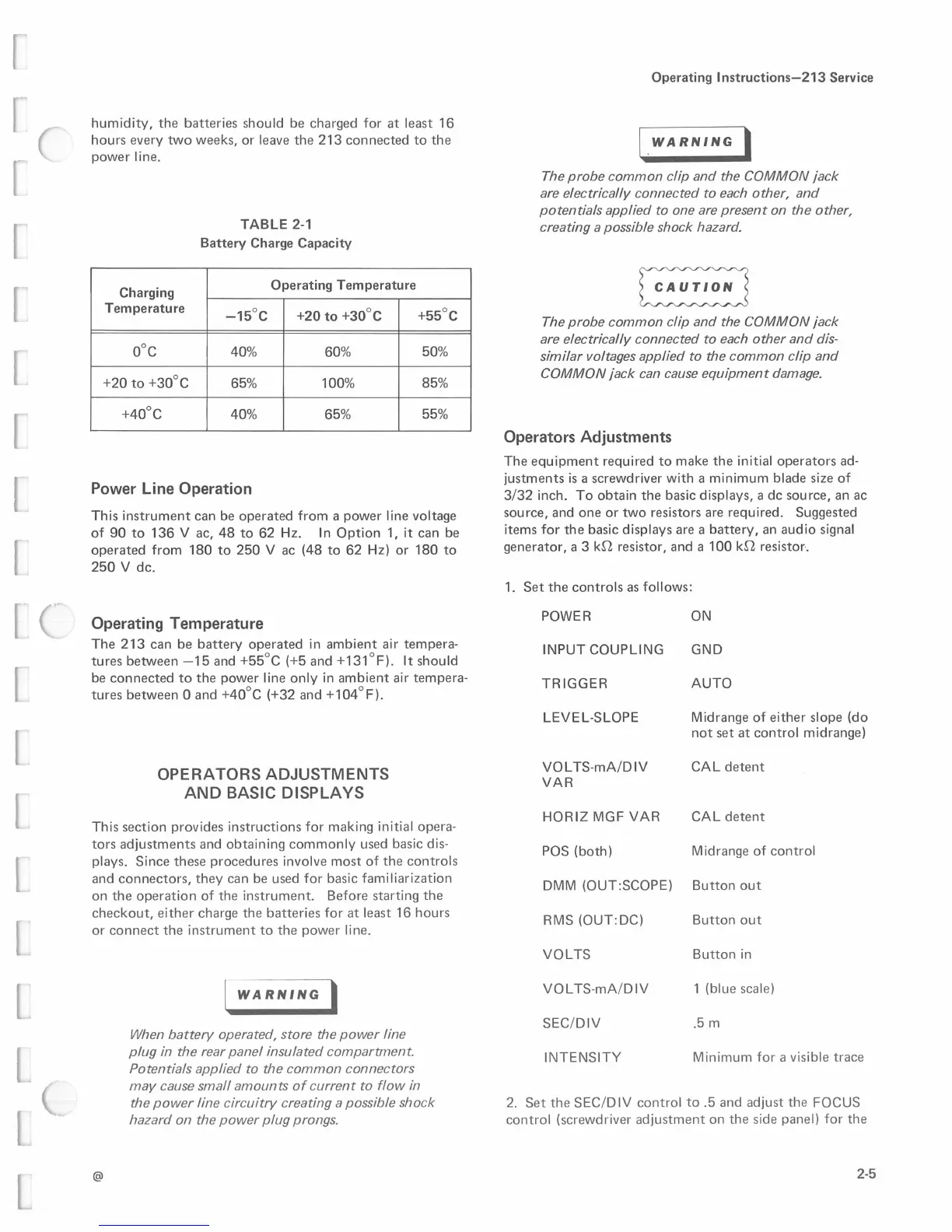
Charging
Temperature
0°C
+20
to
+30°C
+40°C
TABLE 2-1
Battery Charge Capacity
Operating Temperature
-15°C
+20
to
+30°C
40%
60%
65% 100%
40%
65%
+55°C
50%
85%
55%
Power Line Operation
This
instrument
can
be
operated
from
a
power
line voltage
of
90
to
136
V ac,
48
to
62
Hz.
In
Option
1,
it
can
be
operated
from
180
to
250
V
ac
(48
to
62
Hz)
or
180
to
250
V
de.
Operating Temperature
The
213
can
be
battery
operated
in
ambient
air
tempera-
tures
between
-15
and
+55°C
(+5
and
+131°F).
It
should
be
connected
to
the
power
line
only
in
ambient
air
tempera-
tures
between
O
and
+40°C
(+32
and
+104°F).
OPERATORS
ADJUSTMENTS
AND
BASIC
DISPLAYS
This
section
provides
instructions
for
making
initial
opera-
tors
adjustments
and
obtaining
commonly
used basic dis-
plays.
Since
these
procedures
involve
most
of
the
controls
and
connectors,
they
can
be used
for
basic
familiarization
on
the
operation
of
the
instrument.
Before
starting
the
checkout,
either
charge
the
batteries
for
at
least
16
hours
or
connect
the
instrument
to
the
power
line.
@
I
WARNING
I
When battery operated, store the power line
plug
in
the
rear
panel insulated compartment.
Potentials applied
to
the common connectors
may
cause small amounts
of
current to flow
in
the power line circuitry creating a possible shock
hazard on the power plug prongs.
Operating
lnstructions-213
Service
I _
WARNING
I
The probe common clip and the COMMON jack
are
electrically connected to each other, and
potentials applied to one
are
present on the other,
creating a possible shock hazard.
~
The probe common clip and the COMMON jack
are
electrically connected to each other and
dis-
similar voltages applied to the common clip and
COMMON jack
can
cause equipment damage.
Operators Adjustments
The
equipment
required
to
make
the
initial
operators
ad-
justments
is
a screwdriver
with
a
minimum
blade
size
of
3/32
inch.
To
obtain
the
basic displays, a
de
source,
an ac
source,
and
one
or
two
resistors are
required.
Suggested
items
for
the
basic
displays
are a
battery,
an
audio
signal
generator,
a 3
kn
resistor,
and
a
100
kn
resistor-.
1.
Set
the
controls
as follows:
POWER
ON
GND
AUTO
INPUT
COUPLING
TRIGGER
LEVEL-SLOPE
Midrange
of
either
slope
(do
not
set
at
control
midrange)
VOLTS-mA/DIV
CAL
detent
VAR
HORIZ
MGF
VAR
CAL
detent
POS
(both)
Midrange
of
control
DMM
(OUT:SCOPE)
Button
out
RMS
(OUT:DC)
Button
out
Button
in
1 (blue scale)
.5 m
VOLTS
VOLTS-mA/DIV
SEC/DIV
INTENSITY
Minimum
for
a visible
trace
2.
Set
the
SEC/0
IV
control
to
.5
and
adjust
the
FOCUS
control
(screwdriver
adjustment
on
the
side panel)
for
the
2-5
 Loading...


