R
UNKNOWN
J125
J120
OHMS
SCALING
RESISTORS
R120, R121,
R122,R123
R165
S160
[ill
I
I
I
Theory
of
Operation-213
Service
0214,
0215
PRECISION
CURRENT
GENERATOR
0.5mA
1481-9
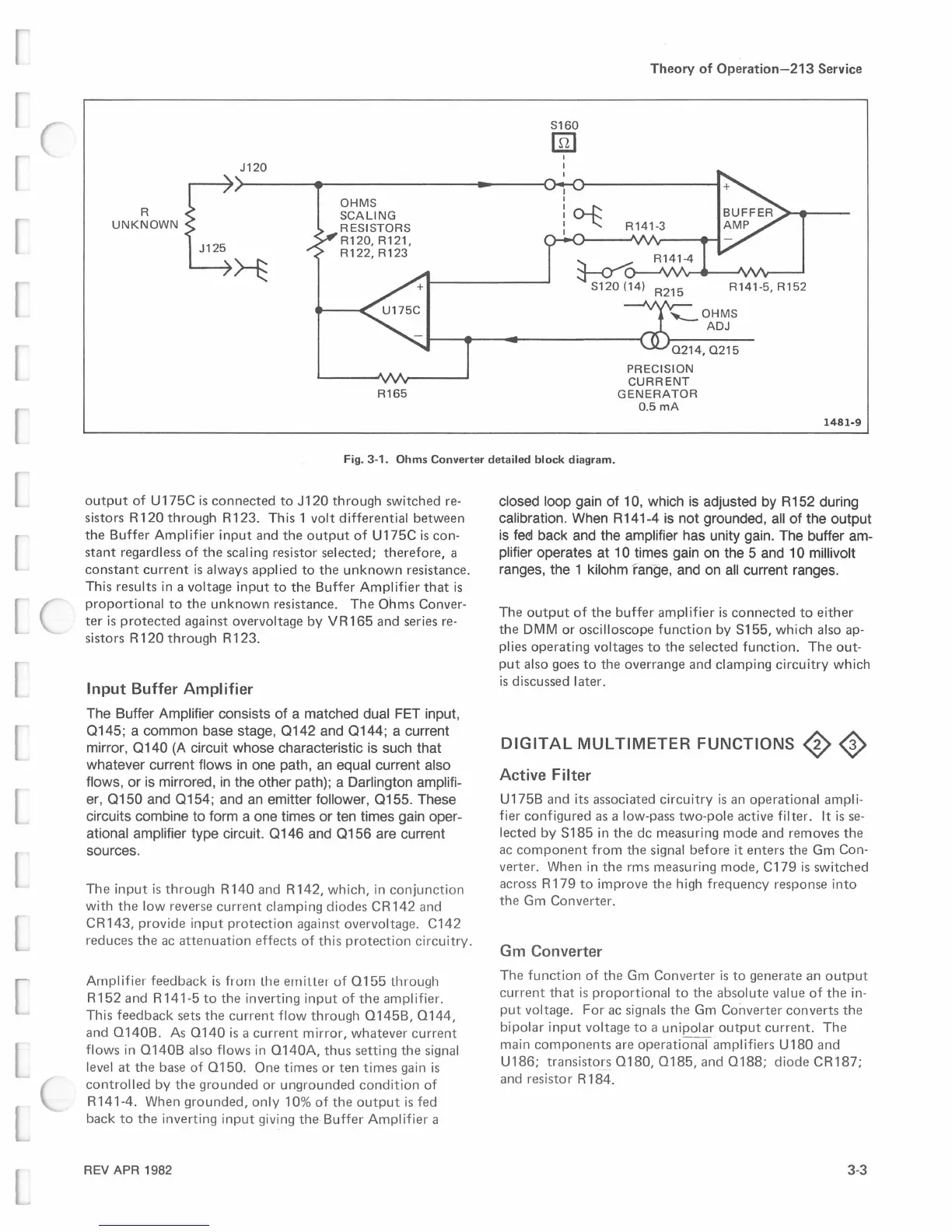
Fig. 3-1. Ohms Converter detailed block diagram.
output
of
U
175C
is
connected
to
J120
through
switched
re-
sistors
R
120
through
R
123.
This
1
volt
differential
between
the
Buffer
Amplifier
input
and
the
output
of
U175C
is
con-
stant
regardless
of
the
scaling
resistor
selected;
therefore,
a
constant
current
is
always
applied
to
the
unknown
resistance.
This
results
in a
voltage
input
to
the
Buffer
Amplifier
that
is
proportional
to
the
unknown
resistance.
The
Ohms
Conver-
ter
is
protected
against
overvoltage
by
VR165
and
series re-
sistors
R
120
through
R
123.
Input Buffer Amplifier
The Buffer Amplifier consists of a matched dual
FET
input,
0145;
a common base stage,
0142
and
0144;
a current
mirror,
0140
(A
circuit whose characteristic
is
such that
whatever current flows
in
one path,
an
equal current also
flows, or
is
mirrored,
in
the other path); a Darlington amplifi-
er,
0150
and
0154;
and
an
emitter follower, 0155. These
circuits combine to form a one times or ten times gain oper-
ational amplifier type circuit.
0146
and
0156
are current
sources.
The
input
is
through
R
140
and
R
142,
which,
in
conjunction
with
the
low
reverse
current
clamping
diodes
CR142
and
CR
143,
provide
input
protection
against
overvoltage.
C142
reduces
the
ac
attenuation
effects
of
this
protection
circuitry.
Amplifier
feedback
is
frorn
Lhe
ernillet
of
0155
Lhrough
R152
and
R141-5
to
the
inverting
input
of
the
amplifier.
This
feedback
sets
the
current
flow
through
O145B,
0144,
and
O140B.
As
0140
is
a
current
mirror,
whatever
current
flows
in
O140B
also
flows
in
O140A,
thus
setting
the
signal
level
at
the
base
of
0150.
One
times
or
ten
times
gain
is
controlled
by
the
grounded
or
ungrounded
condition
of
R
141-4.
When
grounded,
only
10%
of
the
output
is
fed
back
to
the
inverting
input
giving
the
Buffer
Amplifier
a
REV APR 1982
closed loop gain of 10, which
is
adjusted
by
R152 during
calibration. When R141-4
is
not grounded,
all
of the output
is
fee:1
back and the amplifier has unity gain. The buffer am-
plifier operates at 1 0 times gain
on
the 5 and 1 0 millivolt
ranges, the 1 kilohm range, and
on
all
current ranges.
The
output
of
the
buffer
amplifier
is
connected
to
either
the
DMM
or
oscilloscope
function
by
S155,
which
also ap-
plies
operating
voltages
to
the
selected
function.
The
out-
put
also
goes
to
the
overrange
and
clamping
circuitry
which
is
discussed
later.
DIGITAL
MULTIMETER
FUNCTIONS
0
<J>
Active Filter
U175B
and
its
associated
circuitry
is
an
operational
ampli-
fier
configured
as a low-pass
two-pole
active filter. It
is
se-
lected
by
S185
in
the
de
measuring
mode
and
removes
the
ac
component
from
the
signal
before
it
enters
the
Gm
Con-
verter.
When
in
the
rms
measuring
mode,
C179
is
switched
across R
179
to
improve
the
high
frequency
response
into
the
Gm
Converter.
Gm
Converter
The
function
of
the
Gm
Converter
is
to
generate
an
output
current
that
is
proportional
to
the
absolute
value
of
the
in-
put
voltage.
For
ac signals
the
Gm
Converter
converts
the
bipolar
input
voltage
to
a
unipolar
output
current.
The
main
components
are
operational
amplifiers
U 180
and
U186;
transisto
_
~s
0180, 0185,
and
0188;
diode
CR187;
and
resistor
R
184.
3-3
 Loading...


