Performance
Check-213
Service
8.
VERTICAL
SYSTEM
Equipment Required
1.
Amplitude
Calibrator
2.
Sine-Wave Generator
3.
Probe Adapter
4. Screwdriver
5.
Low-Capacitance Screwdriver
6.
Attenuator,
5X
7.
Termination,
Feedthrough
8.
Adapter, Banana Plug
Control Settings
POWER
DMM
RMS
VOLTS
VOL
TS-mA/D
IV
INPUT
COUPLING
INTENSITY
ON
Button
in
Button
out
Button
in
0.1
(blue
scale)
GND
Minimum
for
a visible
display
1.
CHECK/ADJUST
DC
BALANCE
a.
Alternately
select the 0.1 V and 1 V range (blue
scale)
on the
VOL
TS-mA/D
IV
switch.
b.
CHECK-Display
has
the
same
count
(approximately
zero) and
polarity
sign in both switch positions.
c.
ADJUST
-DC
BAL
(side-panel screwdriver adjust-
ment)
for
the
same
count
and
polarity
indication.
2.
CHECK
VERTICAL
DEFLECTION ACCURACY
a.
Set: DMM
INPUT
COUPLING
VOLTS-mA/DIV
SEC/DIV
LEVEL-SLOPE
REV.
A,
JUNE,
1976
Button
out
DC
20 m (black
scale)
1 m
Midrange
of
either slope
(do
not
set at midrange
of
the
control)
b.
Connect the probe
to
the
Amplitude
Calibrator
with
a
probe adapter. Set the Calibrator
for
an
output
of
1 kHz
and
adjust
for
a stable display.
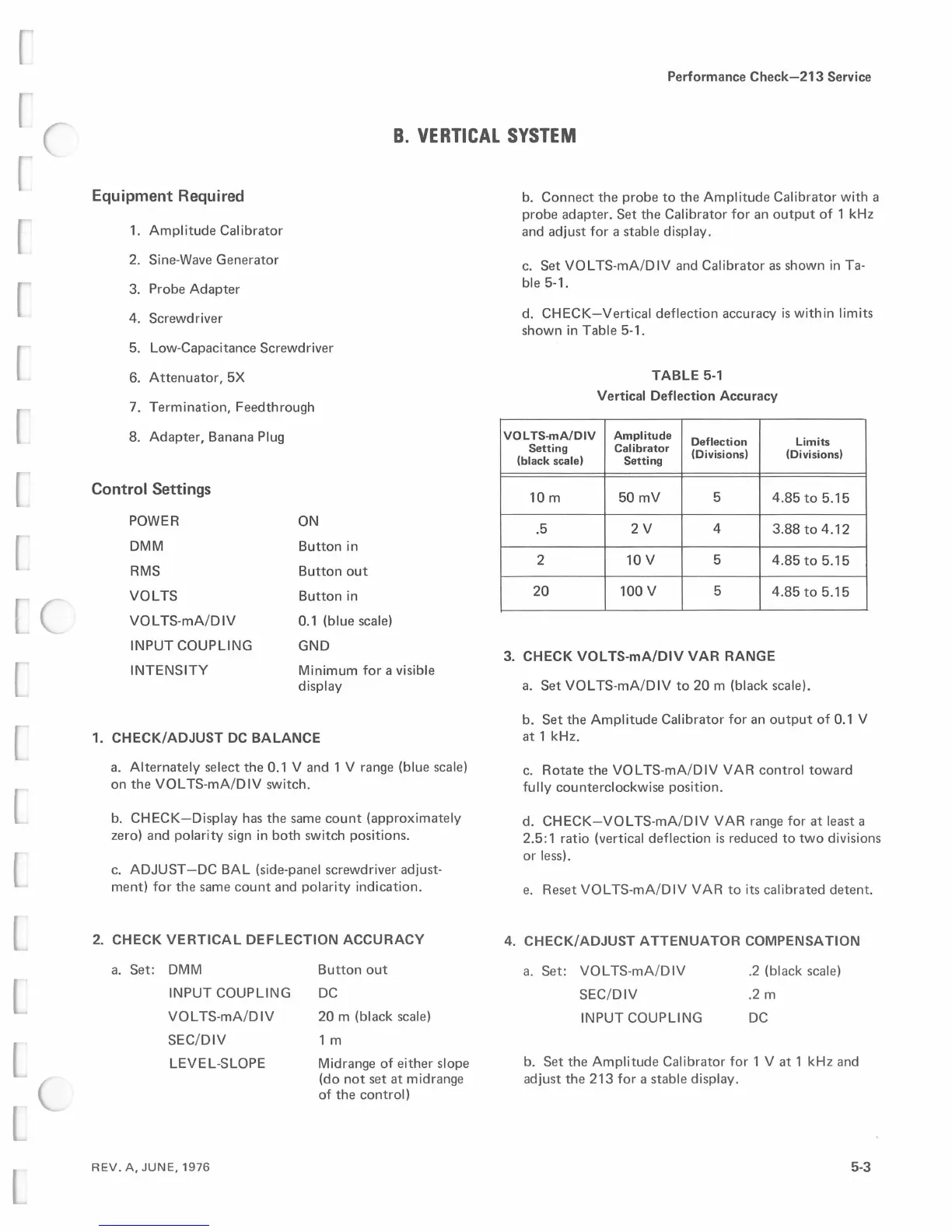
c.
Set
VOL
TS-mA/DIV
and
Calibrator
as
shown in Ta-
ble 5-1.
d.
CHECK-Vertical
deflection accuracy
is
within
limits
shown in Table 5-1.
TABLE
5-1
Vertical Deflection
Accuracy
VOLTS-mA/DIV
Amplitude
Deflection Limits
Setting Calibrator
(Divisions) (Divisions)
(black scale) Setting
10m
50mV
5
4.85
to
5.15
.5
2V
4
3.88
to
4.12
2
10 V 5
4.85
to
5.15
20
100 V 5
4.85to5.15
3.
CHECK
VOL
TS-mA/DIV
VAR
RANGE
a.
Set
VOL
TS-mA/DIV
to
20
m (black scale).
b. Set the
Amplitude
Calibrator
for
an
output
of
0.1
V
at 1 kHz.
c.
Rotate the
VOLTS-mA/DIV
VAR
control
toward
fully
counterclockwise position.
d.
CHECK-VOL
TS-mA/DIV
VAR
range
for
at least a
2.5: 1 ratio (vertical deflection
is
reduced
to
two
divisions
or
less).
e.
Reset
VOL
TS-mA/D
IV
VAR
to
its calibrated detent.
4. CHECK/ADJUST
ATTENUATOR
COMPENSATION
a.
Set:
VOLTS-mA/DIV
SEC/DIV
INPUT
COUPLING
.2
(black
scale)
.2 m
DC
b.
Set the
Amplitude
Calibrator
for
1 V at 1 kHz
and
adjust the 213
for
a stable display.
5-3
 Loading...


