Operation
Table 2-1 (cont’d)
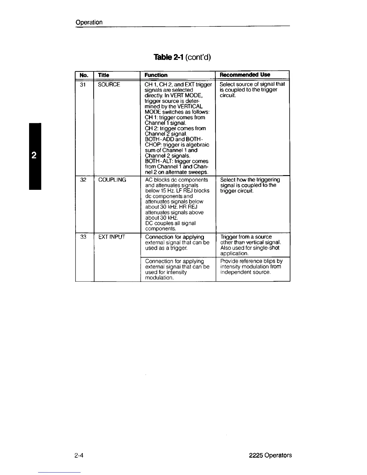
No.
Title
Function
Recommended Use
31
SOURCE CH 1, CH 2, and EXT trigger
signals are selected
directly. In VERT MODE,
trigger source is deter
mined by the VERTICAL
MODE switches as follows:
CH 1: trigger comes from
Channel 1 signal.
CH 2: trigger comes from
Channel 2 signal.
BOTH-ADD and BOTH-
CHOP: trigger is algebraic
sum of Channel 1 and
Channel 2 signals.
BOTH-ALT: trigger comes
from Channel 1 and Chan
nel 2 on alternate sweeps.
Select source of signal that
is coupled to the trigger
circuit.
32
COUPLING
AC blocks dc components
and attenuates signals
below 15 Hz. LF REJ blocks
dc components and
attenuates signals below
about 30 kHz. HR REJ
attenuates signals above
about 30 kHz.
DC couples all signal
components.
Select how the triggering
signal is coupled to the
trigger circuit.
33 EXT INPUT Connection for applying
external signal that can be
used as a trigger.
Trigger from a source
other than vertical signal.
Also used for single-shot
application.
Connection for applying
external signal that can be
used for intensity
modulation.
Provide reference blips by
intensity modulation from
independent source.
2-4 2225 Operators