Applications
3. Set VERTICAL MODE switches to BOTH-NORM-ALT; set both
VOLTS/DIV switches equally to produce displays of approx
imately four or five divisions amplitude.
4. Adjust the CH 2 VOLTS/DIV switch and CH 2 VOLTS/DIV vari
able control so that the Channel 2 display is approximately the
same amplitude as the undesired portion of the Channel 1 dis
play (see Figure 3-3 top).
5. Now set the middle and right VERTICAL MODE switches to CH
2 INVERT and ADD. Slightly readjust the CH 2 VOLTS/DIV vari
able control for maximum cancellation of the undesired signal
component (Figure 3-3 bottom).
Amplitude Comparison (Ratio)
In some applications it may be necessary to establish a set of
deflection factors in between step settings of the VOLTS/DIV
switch. This is useful for comparing unknown signals to a refer
ence signal of known amplitude.
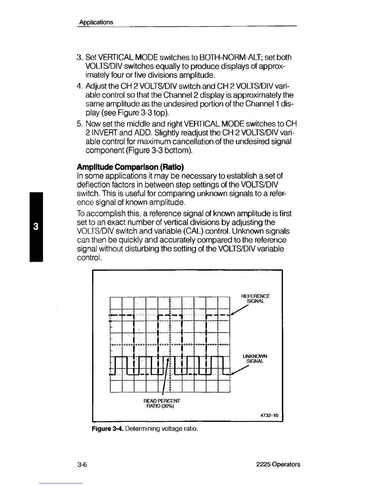
To accomplish this, a reference signal of known amplitude is first
set to an exact number of vertical divisions by adjusting the
VOLTS/DIV switch and variable (CAL) control. Unknown signals
can then be quickly and accurately compared to the reference
signal without disturbing the setting of the VOLTS/DIV variable
control.
READ PERCENT
RATIO (30%)
4732-10
Figure 3-4. Determining voltage ratio.
3-6
2225 Operators