Applications
NOTE
If the measurements are to be made relative to a volt
age level other than ground, set the input coupling
switch to DC and apply the reference voltage to the
input connector. Then position the trace to the hori
zontal reference line.
4. Set the input coupling switch to DC. Points on the waveform
above the ground reference location are positive. Those points
below are negative.
NOTE
If using Channel 2, ensure that the center VERTICAL
MODE switch is set to NORM.
5. If necessary, repeat Step 3 using a different horizontal ground-
reference line that allows the waveform in Step 4 to be dis
played on screen.
6. Adjust the TRIGGER LEVEL control to obtain a stable display.
7. Set the SEC/DIV switch to a position that displays several
cycles of the signal.
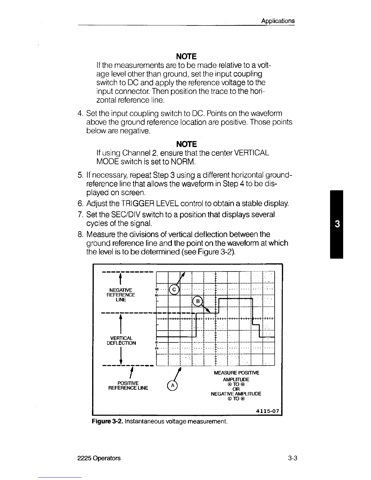
8. Measure the divisions of vertical deflection between the
ground reference line and the point on the waveform at which
the level is to be determined (see Figure 3-2).
t
J
&
LINE
1
VERTICAL
DEFLECTION
h
1
1 '
POSITIVE
REFERENCE LINE
MEASURE POSITIVE
AMPLITUDE
® TO ®
OR
NEGATIVE AMPLITUDE
© TO ®
4 1 1 5 - 0 7
Figure 3-2. Instantaneous voltage measurement.
2225 Operators
3-3