Checks and Adjustments
5. Using the approximately 1-kHz probe-adjustment square
wave as the input, obtain a 5-division display of the signal.
6. Set the SEC/DIV switch to display several cycles of the signal.
Use the Channel 1 POSITION control to vertically center the
display.
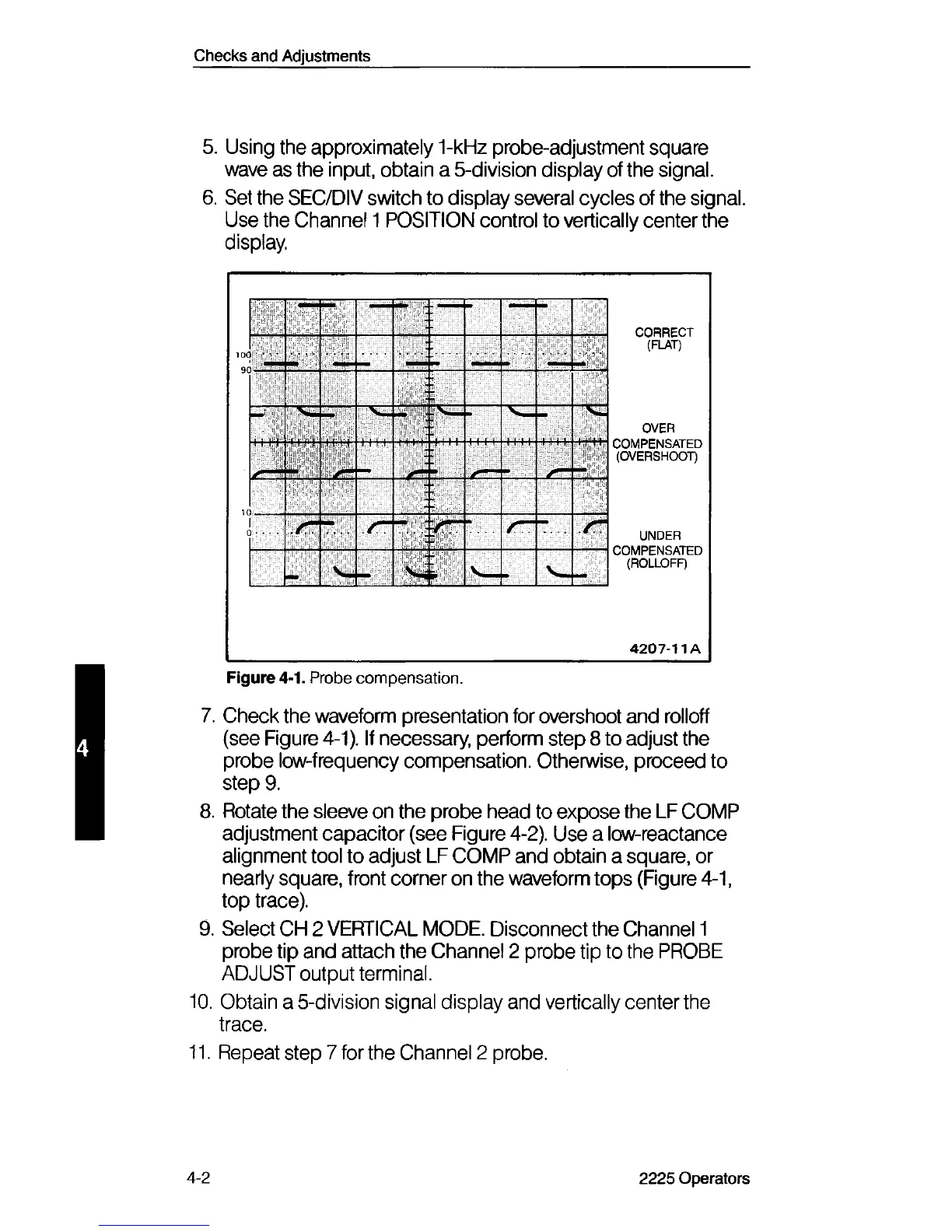
Figure 4-1. Probe compensation.
7. Check the waveform presentation for overshoot and rolloff
(see Figure 4-1). If necessary, perform step 8 to adjust the
probe low-frequency compensation. Otherwise, proceed to
step 9.
8. Rotate the sleeve on the probe head to expose the LF COMP
adjustment capacitor (see Figure 4-2). Use a low-reactance
alignment tool to adjust LF COMP and obtain a square, or
nearly square, front corner on the waveform tops (Figure 4-1,
top trace).
9. Select CH 2 VERTICAL MODE. Disconnect the Channel 1
probe tip and attach the Channel 2 probe tip to the PROBE
ADJUST output terminal.
10. Obtain a 5-division signal display and vertically center the
trace.
11. Repeat step 7 for the Channel 2 probe.
4-2
2225 Operators