Performance Check
Table
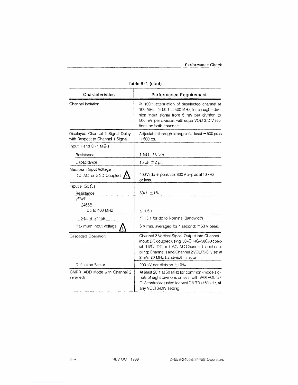
6-1
(cont)
Characteristics
Channel Isolation
Displayed Channel
2
Signal Delay
with Respect
to
Channel 1 Signal
Input Rand
C
(1
MX!)
Resistance
Capacitance
Maximum Input Voltage
.
DC.
AC.
or
GND Coupled
^
Input R
(50 ft)
Resistance
VSWR
2465B
Dc to 400 MHz
2455B 2445B
Maximum Input Voltage
A
Cascaded Operation
Deflection Factor
CMRR
(ADD
Mode with Channel
2
inverted)
Performance Requirement
•^
100:1
attenuation
of
deselected channel
at
100 MHz;
>
50:1
at
400 MHz,
for
an eight-divi-
sion input signal from
5 mV per
division
to
500
mV per
division, with equal VOLTS/DIV set-
tings
on
both channels.
Adjustable through a range of at least
-
500 ps to
+ 500 ps.
1
Mil ±0
5%.
15
pF
±2pF.
400V(dc
+
peakac). 800 Vp-pac at 10kHz
or less.
50X2 ±1%.
<
1.5:1
£1.3:1 fordc
to
Nominal Bandwidth
5
V
rms. averaged
for
1
second:
±50 V
peak.
Channel
2
Vertical Signal Output into Channel
1
input: DC coupled using 50-XI RG-58C/U coax-
ial.
1
MPt DC or
1
MX! AC
Channel
1
input
cou-
pling;
Channel
1
and Channel
2
VOLTS'DIV set at
2 mV:
20
MHz bandwidth limit
on.
200 jiiV
per
division ±10%.
At least 20:1
at
50 MHz
for
common-mode
sig-
nals
of
eight divisions
or
less, with VAR VOLTS/
DIV control adjusted for best CMRR at 50 kHz,
at
any VOLTS/DIV setting.
6-4 REV OCT 1989 2465B/2455B/2445B Operators
 Loading...


