Performance Characteristics
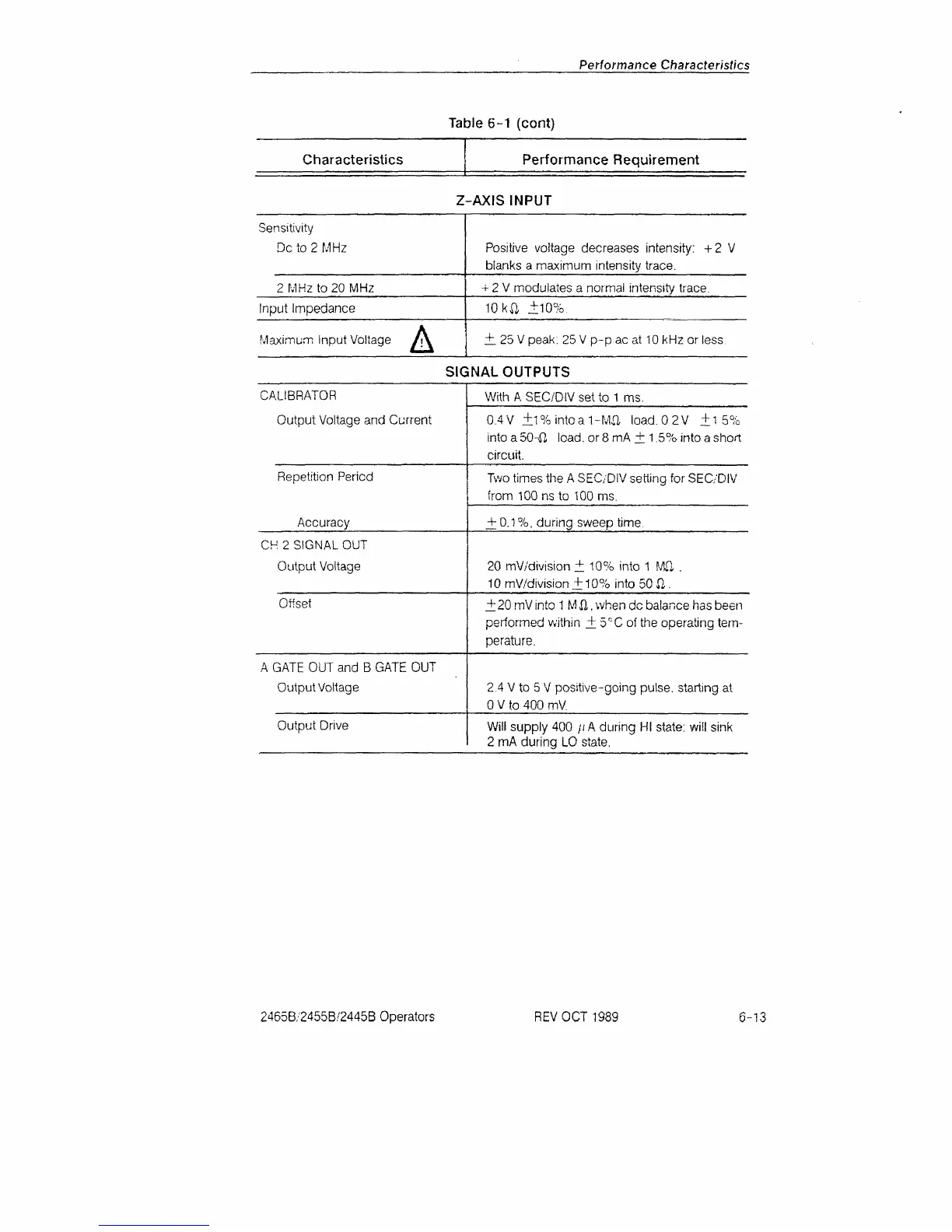
Table 6-1 (cont)
Characteristics Performance Requirement
Z-AXIS INPUT
Sensitivity
Dc
to 2
MHz
2 MHz
to
20 MHz
Input Impedance
Maximum Input Voltage
f\
Positive voltage decreases intensity:
+2 V
blanks
a
maximum intensity trace.
-r
2 V
modulates
a
normal intensity trace.
10kft
±10%.
± 25
V
peak: 25Vp-pacat 10 kHz
or
less
SIGNAL OUTPUTS
CALIBRATOR
Output Voltage and Current
Repetition Period
Accuracy
CH
2
SIGNAL OUT
Output Voltage
Offset
A GATE OUT and
B
GATE
OUT
Output Voltage
Output Drive
With
A
SEC/DIV set
to
1
ms.
0.4 V ±1 % into a
1
-
Mil
load.
0 2V ±1 5%
into
a
50-fi.
load,
or
8 mA
+
1.5% into a short
circuit.
Two times the A SEC/DIV setting
for
SEC/DIV
from 100
ns to
100
ms.
+
0.1
%, during sweep time.
20 mV/division
±
10% into 1
Mfl .
10 mV/division
±
10% into 50
SI.
±
20
mV into
1 M
il,
when
dc
balance has been
performed within
.+ 5
r;
C of
the operating
tem-
perature.
2.4
V to 5 V
positive-going pulse, starting
at
0 V to 400 mV.
Will supply
400
/; A during
HI
state: will sink
2
mA
during LO state.
2465B/2455B/2445B Operators
REV OCT 1989
6-13
 Loading...


