Any module inside of the chassis that does not have a remove and replace procedure requires that the entire instrument be returned to
Tektronix Service Center for service.
Warning: Before performing this or any other procedure in this manual, read the safety summaries found at the beginning of this
manual. Also, to prevent possible injury to service personnel or damage to the instrument components, read Preventing ESD
on page 5.
Before performing any procedure in this subsection, disconnect the power cord from the line voltage source. Failure to do so could
cause serious injury or death.
Note: Read the cleaning procedure before disassembling the instrument for cleaning.
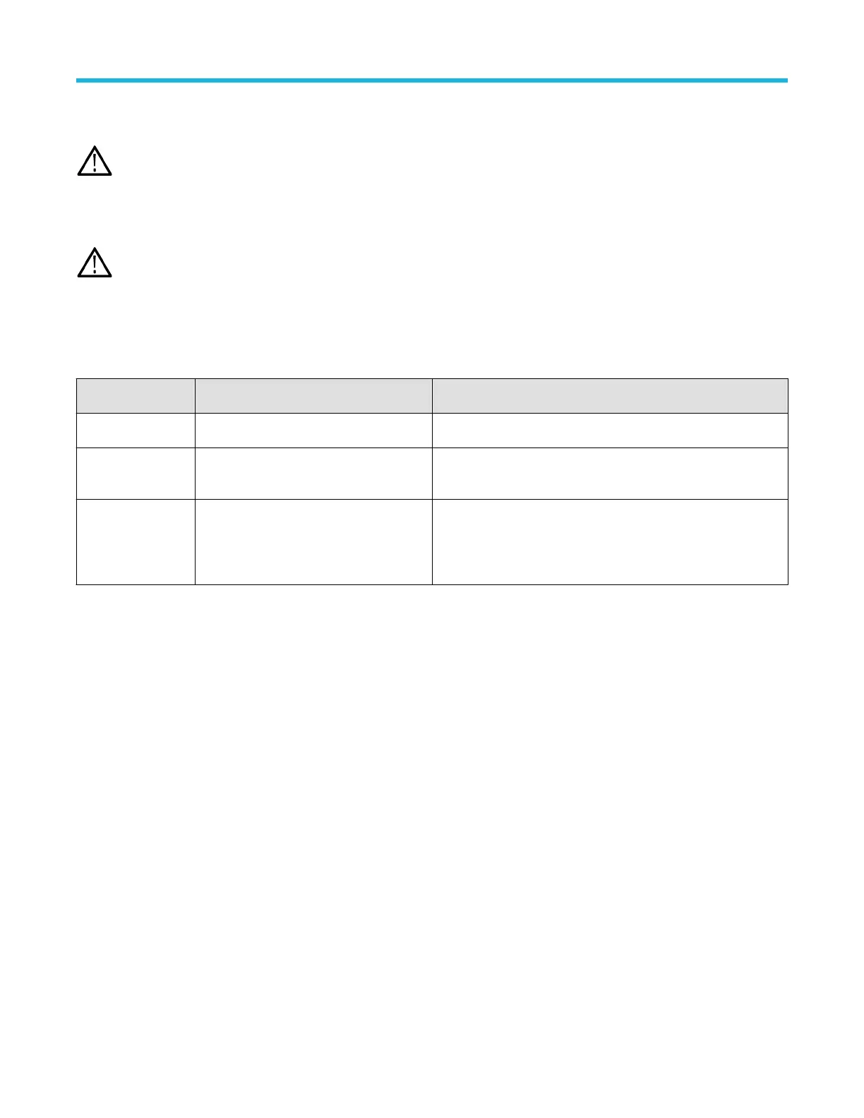
Required equipment
Most assemblies in this instrument can be removed with a T-10 Torx® screwdriver tip.
Table 3: Required equipment for removal and replacement
Item No. Name Description
1 Screwdriver handle Accepts Torx-driver bits
2 T-10 Torx tip Used for removing instrument screws. Torx-driver bit for T-10 size
screw heads
3 Proper antistatic work environment To prevent electrostatic damage to components whenever you work
on the instrument, wear properly-grounded electrostatic prevention
wrist and foot straps, and work in a tested antistatic environment on
an antistatic mat.
Remove feet
Use this procedure to remove and replace bottom feet assemblies or gain access to the rear chassis assembly.
Prerequisite:
• To prevent electrostatic damage to components whenever you work on the instrument, wear properly-grounded electrostatic prevention
wrist and foot straps, and work in a tested antistatic environment on an antistatic mat.
Steps:
Remove the two flip feet assemblies from the rear chassis using the following steps:
1. Remove all cables and the power cord from the rear panel.
2. Set the instrument on its back side so the bottom is facing you.
3. Flip open both feet assemblies.
4. Use a screwdriver with T-10 Torx tip to remove the four screws from each foot assembly.
5. Remove the feet assembles.
6. To reinstall, reverse the steps. Use a screwdriver with T-10 Torx tip to secure the eight screws. First insert and tighten the screws that
are near the front edge of the instrument, then insert and tighten the screws that are near the rear edge of the instrument. Tighten to
0.65 N·m.
Maintenance
3 Series MDO Mixed Domain Oscilloscope Service Manual 8

 Loading...


