• To prevent electrostatic damage to components whenever you work on the instrument, wear properly-grounded electrostatic prevention
wrist and foot straps, and work in a tested antistatic environment on an antistatic mat.
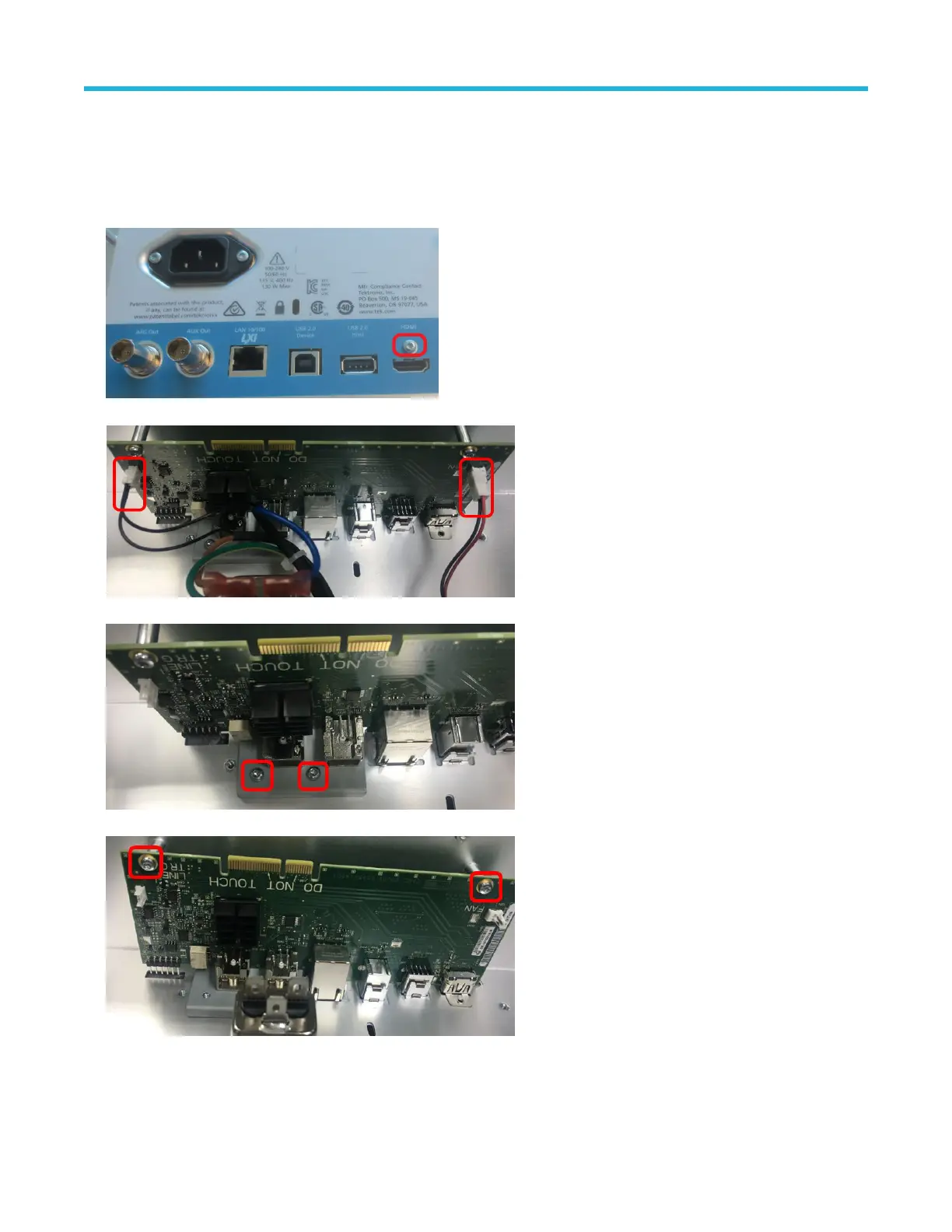
• Remove rear chassis assembly
Steps:
1. Use a T-10 Torx screwdriver to remove the one screw above the HDMI connector on the rear panel.
2. Disconnect the line trigger and fan cable from the I/O board.
3. Use a T-10 Torx screwdriver to remove the two screws above the AFG Out and AUX Out connections.
4. Use a T-10 Torx screwdriver to remove the two screws securing the I/O board to the bottom of the rear chassis.
5. Slide the I/O board out from the rear chasis.
6. To reinstall, reverse the steps. Tighten the T-10 Torx screws to 0.65 N·m when reinstalling.
Maintenance
3 Series MDO Mixed Domain Oscilloscope Service Manual 17
 Loading...


