Table
4-14
VOLTS/DIV
COMPENSATION
Volts/Div Setting
(10X
Scale-Factor)
Adjlust
Time/Div
1 ms
Flat
Time/Div
0.2 ms
Corner
.1 V C37
C36
.2 V C35
C34
.5
V C33 C32
1 V Check
Check
2 V Check
Check
5
V C31 C30
NOTE
If the oscilloscope is to be used primarily with a 50 O
signal source, more accurate reproduction of the
waveform front corner may be achieved by
calibrating with a 50 Cl system. To
accomplish this,
substitute
a
properly terminated 50 fi cable
for the
10X probe while making the front
corner
ad-
justments listed in Table
4-14.
19.
Check/
Adjust CH
2
and Output High-
Frequency Compensation
a. Set:
VOLTS/DIV (both) 5 mV
A TRIGGER SLOPE +
20 MHz BW LIMIT Full bandwidth
(button out)
b. Connect calibration
generator
fast-rise
+
(positive-
going) output to CH 2 input connector via a 50 O bnc
cable, 10X bnc attenuator, and
50
O termination.
NOTE
Adjustments in steps 19 through 25 interact. Perform
all of the checks, but not the adjustments, in these
steps before making any adjustments
(unless
calibration is being performed after repair or
replacement of vertical
components).
If
all checks are within the given limits, proceed to
step 26.
If any of the checks are not within the given limits,
perform checks andadjustments in steps 19 through
25,
using low-capacitance screwdriver.
If
still not within
the
given limits
—
perform steps 6
through 25.
Calibration
Procedure—465B
Service
Adjustment Procedure
c.
Adjust
calibration generator output for a
5-division,
100 kHz
display.
d. Set A TIME/DIV to 0.2 ps.
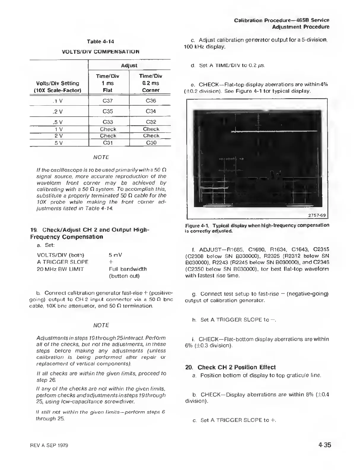
e. CHECK—Flat-top
display aberrations are within 4%
(±0.2 division). See
Figure
4-1
for typical display
2757-69
Figure
4-1.
Typical
display when
hlgh-lrequency compensation
is correctly adjusted.
f. ADJUST—R1 685. C1690,
R1634.
C1643, C2315
(C2308
below SN B030000),
R2325 (R2312 below
SN
B030000)
,
R2243 (R2245
below SN
B030000),
and C2346
(C2350
below SN B030000),
for best flat-top waveform
with fastest rise time.
g.
Connect test setup to fast-rise
—
(negative-going)
output of calibration
generator.
h.
Set A TRIGGER SLOPE to
i. CHECK—Flat-bottom display
aberrations are within
6% (±0.3
division).
20. Check CH 2 Position Effect
a
Position bottom of display to top
graticule line.
b. CHECK—Display
aberrations are within
8% (±0.4
division).
c. Set A TRIGGER
SLOPE to ±.
REV A SEP 1979 435