e.
Upper wire
of
a
pair of wires
between the large
high-voltage capacitors is
white with a brown
stripe.
Maintenance—465B
Service
WARNING
The
crt anode and the
output terminal
of high-
voltage
multiplier may
retain
a
high-voltage
charge
after the
instrument is turned off.
To avoid electrical
shock, ground both
the output
terminal of the
multiplier and the
crt high-voltage
anode lead to
chassis
ground.
9.
Disconnect
horizontal deflection
plate leads at the
crt.
This requires a
pair of long-nose
pliers for best
removal or
reinstallation (pull connectors
straight out
from
pins to avoid strain
on metal-to-glass neck-pin
seal).
10.
Unplug five
connectors from Main
Interface board.
Confirm each wire’s
color and
location in thefollowing
list
for
reassembly reference:
a. J4325,
white with
black
and brown stripes, from
near the
rear
middle of the board.
b. J4387,
white
with a red stri pe,
from near the
front
of the board.
c. J4385,
white with black
and red stripes, from near
the
front of the board.
d. J4388,
white with
a blue
stripe, from near the
front
of the board.
e. J4475,
white with
an orange
stripe, from between
the interboard
connectors
(to
the
Sweep
Timing circuit
board).
11.
Unsolder one
wire from near
the left middle of
the
board (under
cable harness).
12.
Remove
power transistor
mounting screw from
Q4102,
Q4301
,
and
Q4401.
13.
Remove
mounting screw
from transistor Q4312
near the
lower rear
corner of the board.
14.
Remove mounting
screw from transistor Q4190
near the top
right corner of
the board.
15.
Remote
four
hexagonal posts that
stand-off the
high-voltage
shield.
Use a
3/16"
nutdriver.
16. Remove
seven Main
Interface board
mounting
screws. A Phillips
screwdriver is
required.
17.
Disconnect crt
anode-lead plug from
the high-
voltage m
ultiplier jack. Ground this lead to the
instrument
main chassis to remove
any stored
charge. Insert a
medium-size screwdriver
tip between
the multiplier jack
body
and the hold
down spring clip. Pry the
multiplier jack
out of the spring
clip.
18.
Separate Main
Interlace circuit
board from the
instrument chassis, using
care to prevent
damage to
components or
wiring. Carefully thread
interconnecting
cables
through the board
and chassis, as
necessary, to
avoid strain on
any cable. Let
the
board
pivot on
power-
transformer
leads that are
still connected to the
board.
NOTE
You can now
perform
repairs on the
reverse side of
the
Main Interlace
board, if repair
Is intended. To
reinstall the
board, reverse
the order of
the removal
steps. If you
intend to
replace the Main
Interface
circuit
board, continue with
this
procedure.
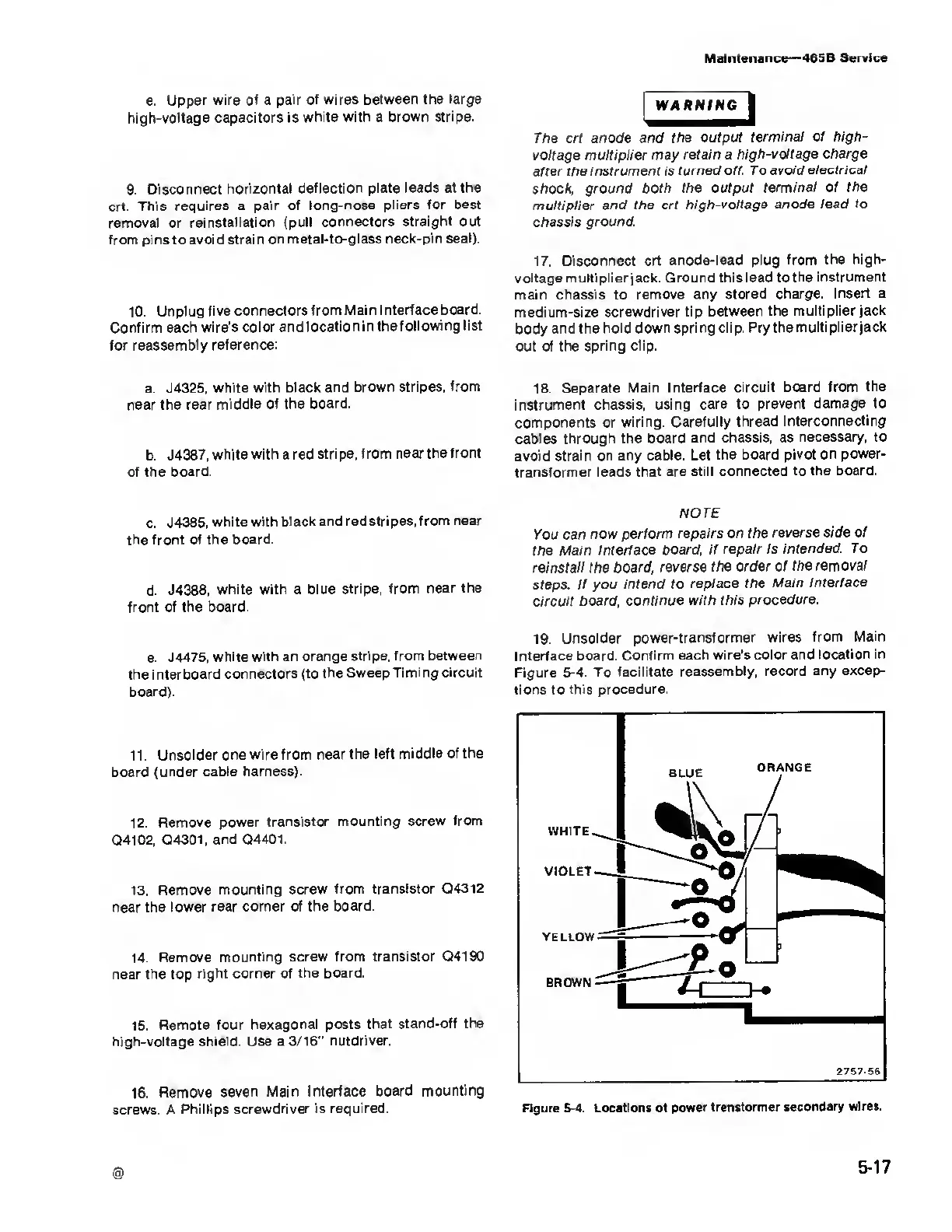
19. Unsolder
power-transformer
wires
from Main
Interface
board. Confirm
each wire’s color and location in
Figure
5-4.
To
facilitate
reassembly, record any
excep-
tions
to
this
procedure.
Figure
5-4.
Locations of power
trensformer secondary
wires.
@
5-17