Getting Acquain
tedwithYourInstrument
Channel C oupling
You can change the parameter values for multiple channels at a time. This function is called Channel Coupling.
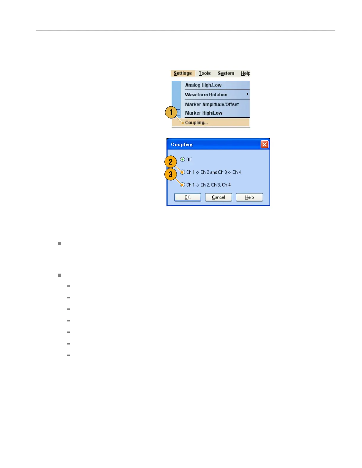
1. Select Settin
gs > Coupling to open the
Coupling dialog box.
You can also open this dialog box
from the pop-
up menu displayed by
right-clicking on the Channel page of the
Settings window.
2. Select a coupling method.
Ch1->Ch2andCh3->Ch4means
that Ch 1 and Ch 2, and Ch 3 and Ch 4
are coupled, respectively.
3. Select Ch1->Ch2,Ch3,Ch4to
couple the Ch 1 parameters with Ch 2,
Ch 3, and Ch 4 parameters.
Quick Tips
Ch1->Ch2,Ch3,Ch4means that Ch 1 parameters are coupled with Ch 2, Ch 3 and Ch 4 parameters. With the
Channel Coupling in the On state, the Ch 1 parameters are applied to the instrument hardware settings of the other
three channels. You cannot select parameters for channel coupling in the Channel page of the Settings window. The
disabled parameters are grayed out.
The following parameters are excluded from channel coupling:
Channel skew
Output waveform
Sequence waveform
External signal add function
Waveform rotation
Marker delay
Parameters that are not related to the output signal, such as marker display on/off
AWG5000 and AWG7000 Series Quick Start User Manual 35

 Loading...


