Probe properties
From the Vertical menu, select Probe Controls, click the Setup button, and then click the Properties button.
To use
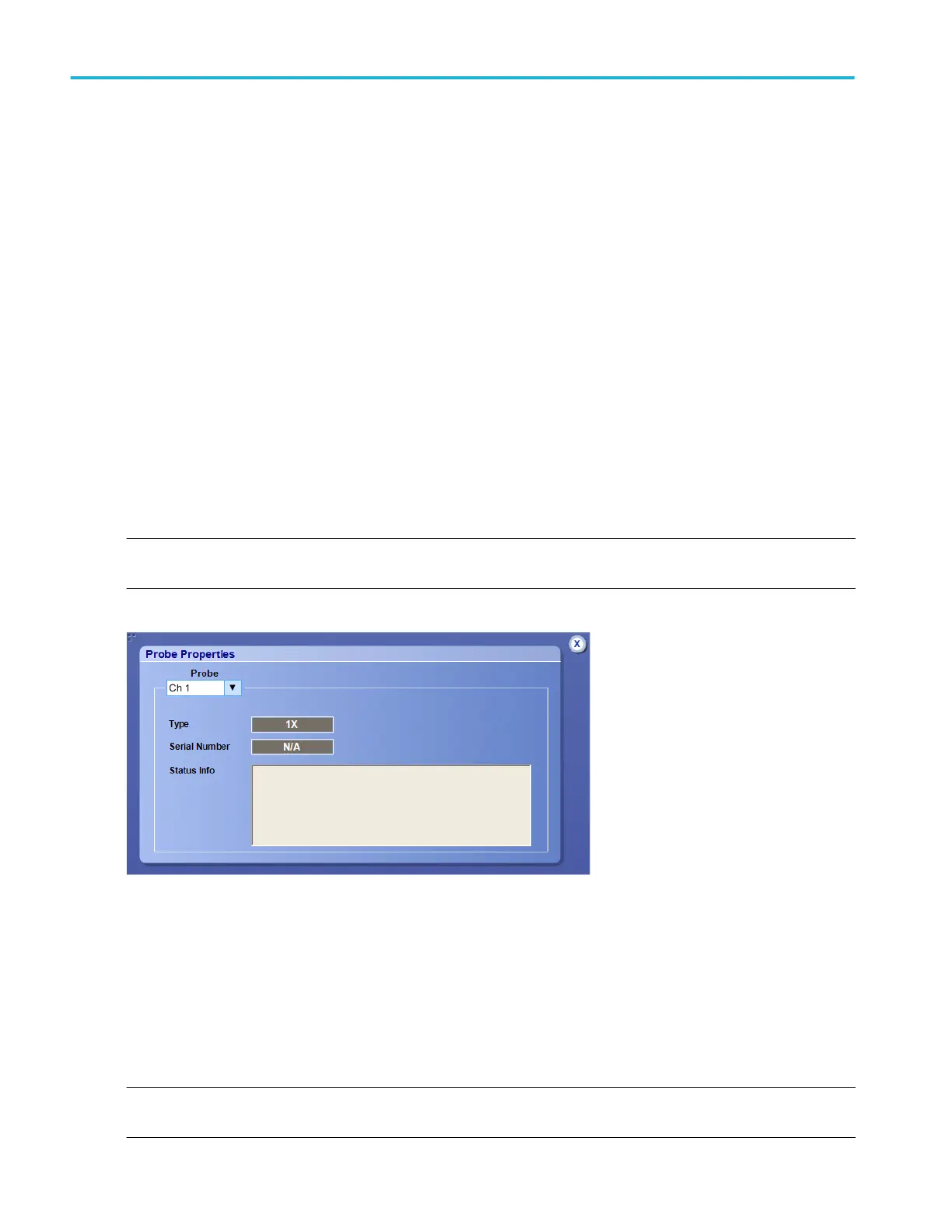
The Probe Properties dialog displays information on the probe attached to the analog or to the digital channels. To view the
probe information, select the channel of interest from the drop-down list of channels under Probe.
The dialog includes the following information for analog probes:
■
Type of probe connected to the selected channel
■
Serial number of the attached probe (for probes with serial numbers)
■
Status information, such as the time you connected the probe, the probe type, the serial number, and compensation results
■
Full text of probe error messages is displayed for compatible probes. Errors may include the following types:
■
Tip fault (Line open, Self-test failure of tip, and Tip broken)
■
Tip temperature change
■
Tip overheating
■
Tip thermal shutdown
NOTE. When the probe is compensated, the instrument polls the probe and displays the serial number. An N/A indicates that the
probe has not been compensated.
The Probe Properties dialog includes the following information for logic probes:
■
Type of logic probe connected
■
Serial number of the logic probe
■
Analog channel selected as the Reference Channel
■
Type of probe connected to the Reference Channel
■
Status of the Analog to Digital Trigger Path Alignment routine
NOTE. The instrument requires the Logic Probe Deskew Fixture (Tektronix part number 067-2083-XX) to run the Analog to
Digital Trigger Path Alignment routine.
Vertical setups
510 DPO70000SX, MSO/DPO70000DX, MSO/DPO70000C, DPO7000C, and MSO/DPO5000B Series
 Loading...

