Performance Ver
ification
Check DVM Frequency Accuracy and M aximum Input Frequency
This test checks DVM Frequency Accuracy.
1. Push Default Setup on the oscilloscope front panel to set the instrument to the factory default s ettings.
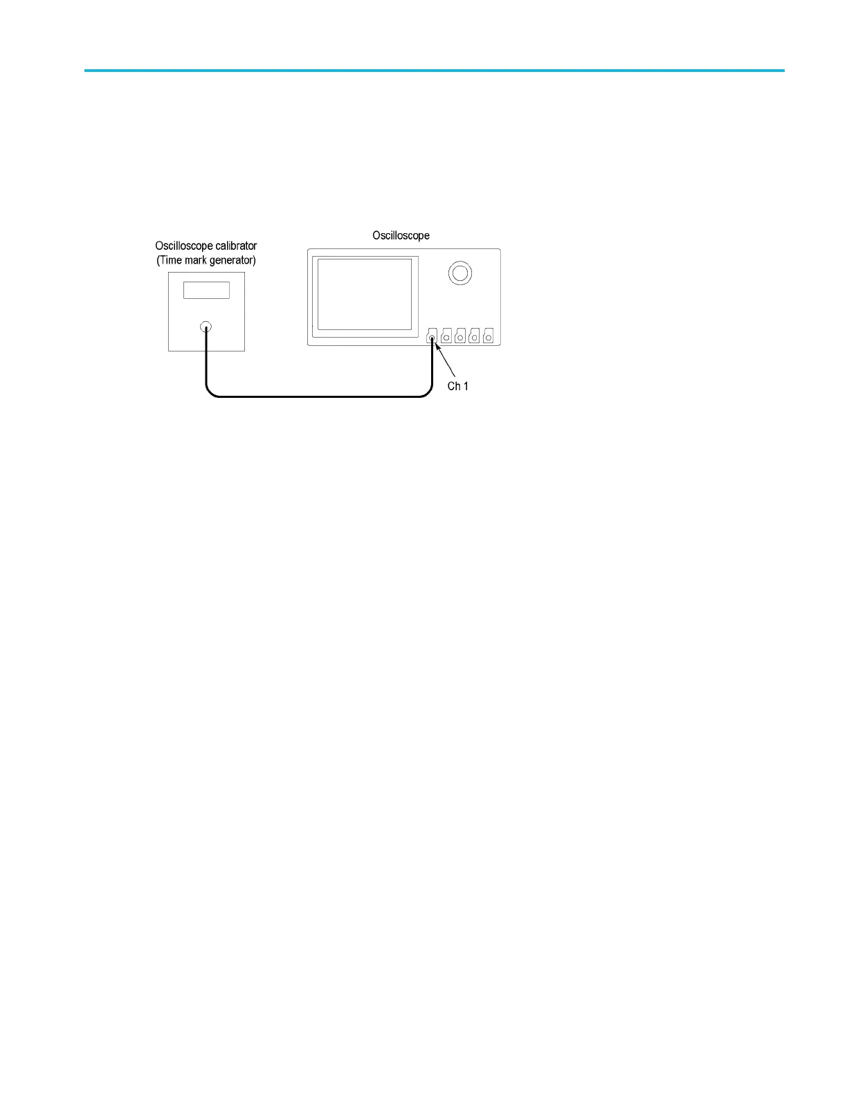
2. Connect the output of the time mark generator to the oscilloscope channel 1 input using a 50 cable. Use the time mark
generator with a 50 source with the oscilloscope set for internal 50 termination.
3. Set the time mark generator to the value shown in the test record. For example, use 9 Hz. Use a time mark waveform
with a fas
t rising edge (square wave), except at 150 MHz use a sine wave.
4. Set the m
ark amplitude to 1 V
pp
.
5. Set the o
scilloscope vertical Scale to 200 mV/div.
6. Set the H
orizontal Scale to 20 m s/div.
7. Adjust
the Trigger Level for a triggered display.
8. Adjust
the vertical Position knob to center the time mark on center screen.
9. Push th
e Measure button on the front panel, and then the DVM lower-bezel button to turn on the DVM feature.
10. Turn mu
ltipurpose knob a to select Frequency mode.
11. Turn m
ultipurpose knob b to select the input channel being tested.
12. Enter
the measured value in the test record.
13. Repea
t this procedure for each frequency setting shown in the record. (Keep the same vertical and horizontal scales
as set in steps 5 and 6.)
14. Repeat all these steps for each oscilloscope channel.
This completes the procedure.
This completes the Performance Verification proced ures
MDO3000 Series S pecifications and Performance Verification 117

 Loading...


