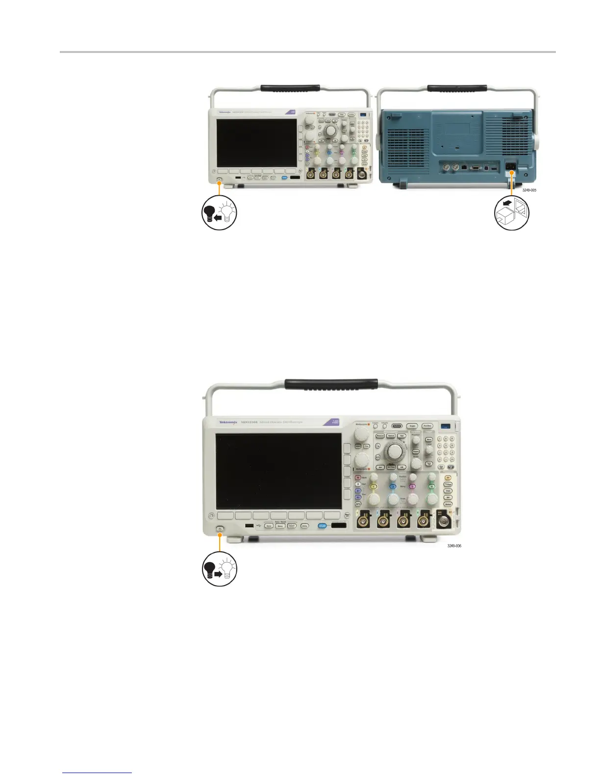
Power-On and Power-Off Procedure
Functional Check
Perform this quick functional check to verify that your oscilloscope is operating
correctly.
1. Connect the oscilloscope power cable as described in Powering On the
Oscilloscope. (See page 22, Power-On and Power-Off Procedure.)
2. Power on the oscilloscope.
3. Connect the proper TPP0250, TPP0500B or TPP1000 probe tip and reference
lead to the PROBE COMP connectors on the oscilloscope.
MDO3000 Installation and Safety Instructions 23
 Loading...


