EasyManuals Logo

Tektronix MDO3024 Installation And Safety Instructions

Tektronix MDO3024
140 pages
To Next Page IconTo Next Page
To Previous Page IconTo Previous Page
Page #33 background imageLoading...
Page #33 background image
Power-On and Power-Off Procedure
1. Connect the osc
illoscope power cable.
2. Power on the oscilloscope.
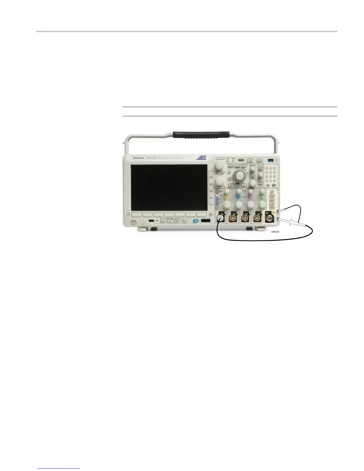
3. Connect the probe connector to the oscilloscope channel, and the probe tip
and reference lead to the PROBE COMP terminals on the oscilloscope
front panel
.
NOTE. Connect only one probe at a time to the probe comp terminals.
4. Push a front panel button for an input channel c onnected to the probe you
wish to compensate. (1, 2, 3,or4)
5. Notice on the lower menu that the oscilloscope has automatically set the
probe termination v alue.
6. Push More repeatedly to se lect Probe Setup from the resulting pop-up menu.
7. Not
ice that the compensation status starts as Default.
8. Push Compensate probe and follow the instructions that appear on the
di
splay.
MDO3000 Installation and Safety Instructions 25

Table of Contents

Other manuals for Tektronix MDO3024

Questions and Answers:

Question and Answer IconNeed help?

Do you have a question about the Tektronix MDO3024 and is the answer not in the manual?

Tektronix MDO3024 Specifications

General IconGeneral
Analog Channels4
Bandwidth200 MHz
Sample Rate2.5 GS/s
Record Length10 Mpoints
Digital Channels16 (optional)
Spectrum Analyzer Frequency Range9 kHz to 3 GHz
Digital Voltmeter4-digit
Vertical Resolution8 bits
Operating Temperature0 °C to +50 °C
Display9-inch WVGA (800x480) color display
ConnectivityUSB, LAN, GPIB (optional)
Arbitrary Function Generator50 MHz
Trigger ModesEdge, Pulse Width, Logic, Video, Runt, Rise/Fall Time, Setup/Hold
Input Impedance1 MΩ ±1%
Max Input Voltage300 VRMS
Trigger TypesEdge, Pulse Width, Logic, Video, Runt, Rise/Fall Time, Setup/Hold

Related product manuals