Get Acquainted w
ith the Instrument
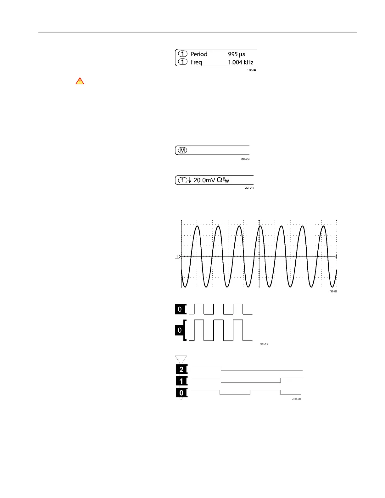
12. Measurement re
adouts show the
selected measurements. You can select
up to eight measurements to d isplay at
one time.
A
symbol appears instead of the
expected numerical measurement if a
vertical cli
pping condition exists. Part
of the waveform is above or below the
display. To obtain a proper numerical
measurement
, turn the vertical scale
and position knobs to make all of the
waveform appear in the display.
13. The auxiliary waveform readouts show
the vertic
al and horizontal scale factors
of the m ath and reference waveforms.
14. The chann
el readout shows the channel
scale factor (per division), coupling,
invert, and bandwidth status. Adjust
with the V
ertical Scale knob and in the
channel 1, 2, 3,or4 menus.
15. For analog channels, the waveform
baseline indicator shows the zero-volt
level of
a waveform, assuming you have
not used any offset. T he icon colors
correspond to the waveform colors.
16. For digital channels, the baseline
indicators point to the high and low
levels. The indicator colors follow the
color code used on resistors. The
D0 indicator is black, the D1 indicator is
brown, the D2 indicator is red, and so on.
17. The g
roup icon indicates when digital
channels are grouped.
MDO4000 Series Oscilloscopes User Manual 45

 Loading...


