Get Acquainted w
ith the Instrument
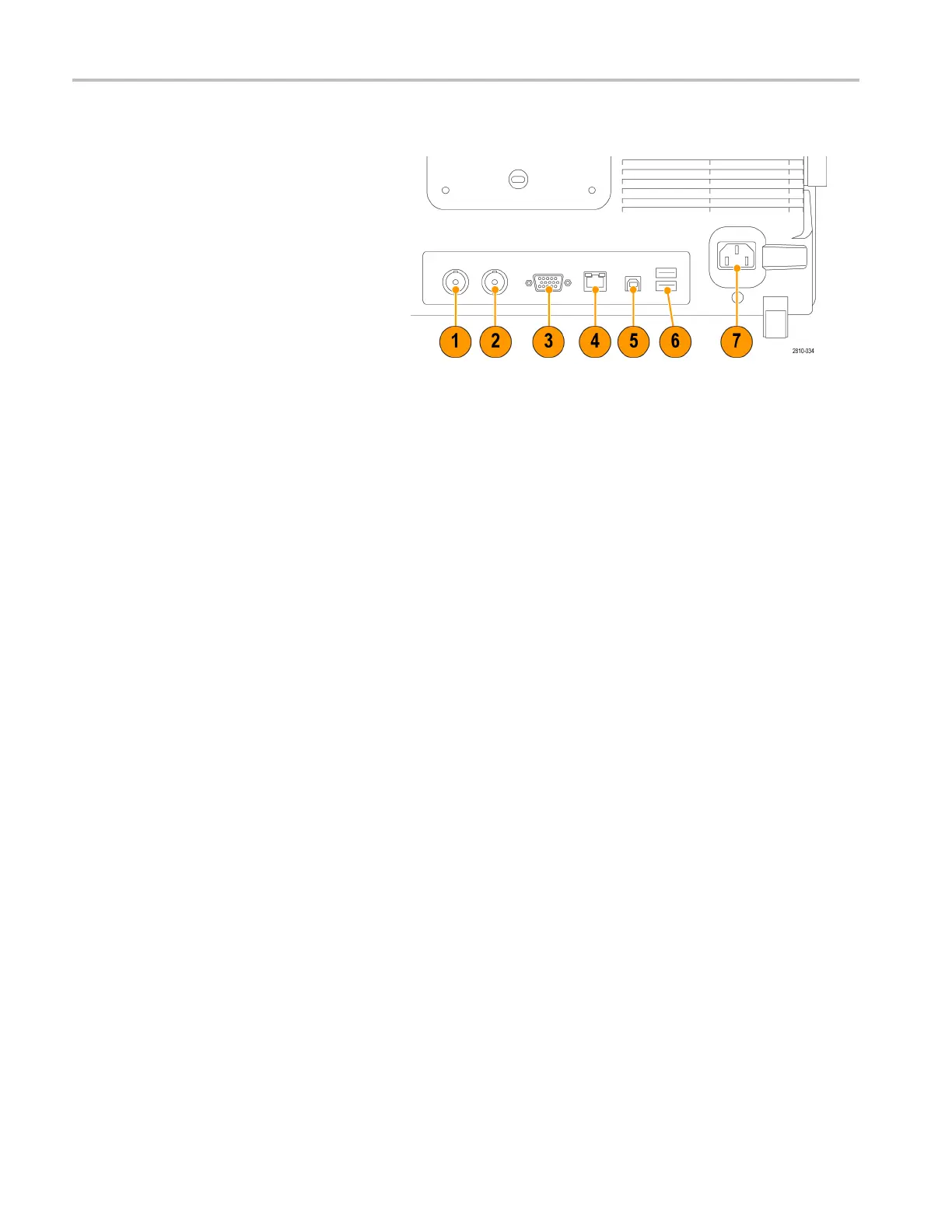
Rear-Panel Connectors
1. Auxiliary Out
put. Use this output to
generate a signal on a main trigger
pulse, as a 10 MHz reference signal,
or to output a s
ignal when other events
happen, such as mask-limit test events.
To use this to synchronize other test
equipment wi
th your oscilloscope,
push the front-panel Utility button,
the bottom-bezel Utility Page button,
and select E
xternal Signals with
multipurpose knob a. Push AUX OUT
from the bottom-bezel menu and Main
Trigger fr
om the resulting side menu.
ALOWtoHIG
H transition indicates that
the trigger occurred. The logic l evel for
Vout (HI) is ≥2.5 V open circuit; ≥1.0 V
intoa50Ω
load to ground. The logic
level for Vout (LO) is ≤0.7 V into a load
of ≤4mA;≤0.25 V into a 50Ω load to
ground.
2. EXT R EF IN. You can connect an external
clock to
this connector. To enable this
connector, push the front-panel Utility
button, the bottom-bezel Utility Page
button
, and select External Signals with
multipurpose knob a. Push Reference
Source from the bottom-bezel menu
and EXT
REF IN from the resulting side
menu.
3. XGA Out. Use the XGA Video port
(DB-15 female connector) to show the
osci
lloscope display on an external
monitor or projector.
4. LAN. Use the LAN (Ethernet) port (RJ-45
connector) to connect the oscilloscope to
a10
/100 Base-T local area network.
MDO4000 models are LXI Class C
version 1.3 compliant.
48 MDO4000 Series Oscilloscopes User Manual

 Loading...


