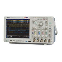
Specifications (MSO/DPO5000 Series)
Table 2-1: Analog channel input and vertical specification (cont.)
Characteristic Description
Upper frequency
limit, 250 MHz
bandwidth
limited, typical
250 MHz, ±20%
Upper frequency
limit, 20 MHz
bandwidth
limited, typical
20 MHz, ±20%
Calculated Rise Time at 350/BW (MHz). The formula is calculated by measuring -3 dB bandwidth of the
oscilloscope. The formula accounts for the rise time contribution of the oscilloscope independent of the rise
time of the signal source.
Instrument
50 Ω
10 mV/div to
1V/div
50 Ω
5 mV/div to
9.98 mV/div
50 Ω
2 mV/div to
4.99 mV/div
50 Ω
1 mV/div to
1.99 mV/div
MSO5204,
DPO5204
175 ps 233 ps 1 ns 2 ns
Instrument
50 Ω
5 mV/div to
1V/div
50 Ω
2 mV/div to
4.99 mV/div
50 Ω
1 mV/div to
1.99 mV/div
MSO5104, DPO5104
350 ps 1 ns 2 ns
MSO5054, DPO5054
700 ps 1 ns 2 ns
MSO5034, DPO5034
1ns 1ns 2ns
Instrument TPP1000 probe
50 mV/div to
100 mV/div
TP1000 probe
20 mV/div to
49.8 m V/div
TPP1000 probe
10 mV/div to
19.9 mV/div
MSO5204, DPO5204
350 ps 1 ns 2 ns
MSO5104, DPO5104
350 ps 1 ns 2 ns
MSO5054, DPO5054
700 ps 1 ns 2 ns
MSO5034, DPO5034
Ins 1ns 2ns
Instrument TPP0500 probe
50 mV/div to
10 V/div
TPP0500 probe
20 mV/div to
49.8 m V/div
TPP0500 probe
10 mV/div to
19.9 mV/div
MSO5204, DPO5204
700 ps 1 ns 2 ns
MSO5104, DPO5104
700 ps 1 ns 2 ns
MSO5054, DPO5054
700 ps 1 ns 2 ns
Calculated rise
time, typical
MSO5034, DPO5034
1ns 1ns 2ns
2–6 MSO70000/C, DSA70000B/C, DPO7000B/C, DPO7000, MSO5000, DPO5000 Series

 Loading...


