Section
4—T912
ADJUSTMENTS
WARNING
SERVICING INFORMATION IN THE
FOLLOWING
SECTIONS IS INTENDED
FOR
USE BY
QUALIFIED
SERVICE PERSONNEL ONLY. TO AVOID
ELECTRIC
SHOOK, DO NOT
REMOVE
INSTRUMENT COVERS
OR PERFORM
ANY SERVICING UNLESS
QUALIFIED TO DO SO.
IMPORTANT—PLEASE READ BEFORE
USING
THIS PROCEDURE
When
done
properly, this
procedure
allows you to adjust the instrument to its original
performance
specifications. The
Adjustment
Procedure
is
not intended
as a
troubleshooting
guide. Any trouble
you
find during the procedure should be corrected
before
continuing. Refer to the Service information section for further information.
LIMITS
AND TOLERANCES
Limits and tolerances are instrument specifications
only if they are called out as performance requirements in
the
Specification section. Tolerances given
are for the
oscilloscope under test and
do
not include test
equipment
error.
ADJUSTMENT INTERACTION
Some adjustments interact with others. These are
identified
with
an
INTERACTION
step.
PARTIAL PROCEDURES
You
can perform part of the
adjustment
procedure after
replacing
components or just to touch up
the performance
between major re-adjustments.
Do
not change the setting
of the
“8
V
supply unless
you
intend
to re-adjust
the entire
instrument.
To adjust
only part of the instrument, set the controls
according to the nearest preceding Control Settings and
use the test
setup
given in the step
you
intend to perform
or the
setup
in a preceding step. To prevent unnecessary
re-adjustment of other parts of the instrument, reset an
adjustment only if the tolerance
given
for
that step is
not
met.
If It is
necessary to reset an adjustment, also check
any steps listed in the INTERACTION
—
part of the step.
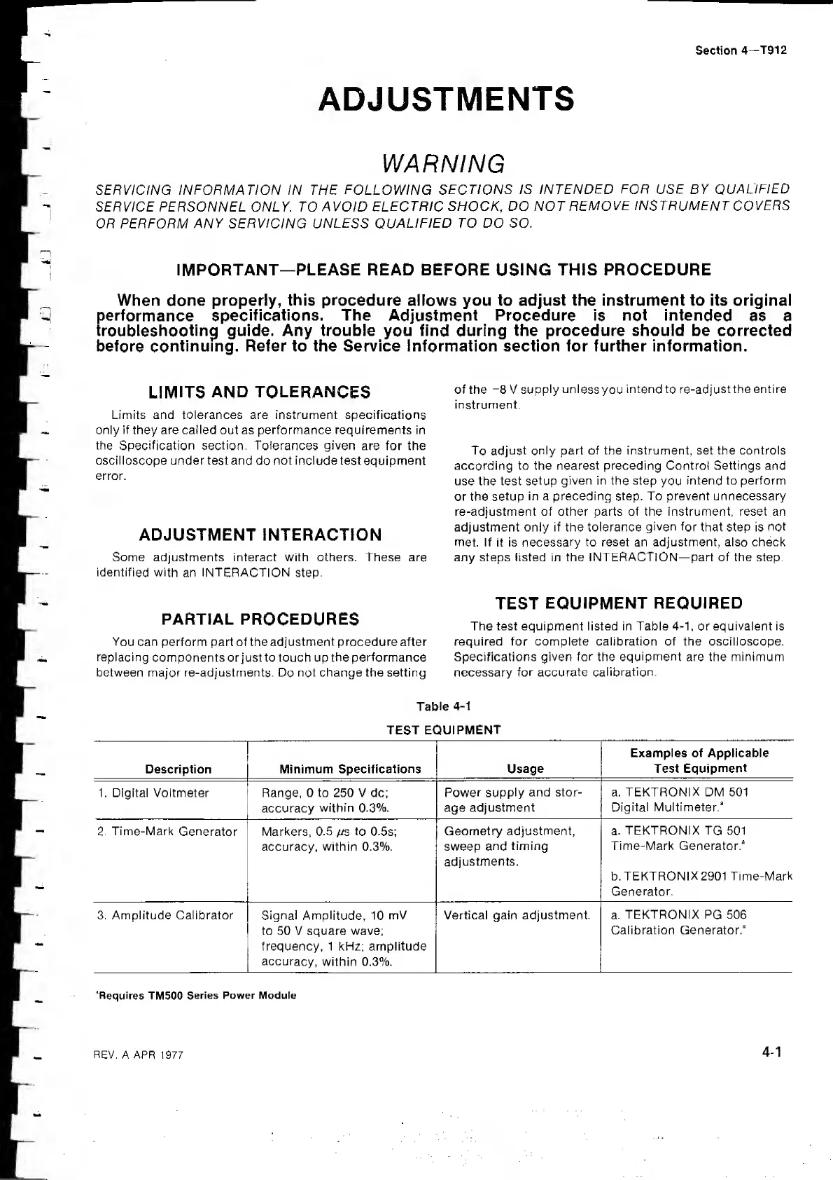
TEST
EQUIPMENT
REQUIRED
The test equipment listed in Table
4-1,
or equivalent is
required for complete calibration of the oscilloscope.
Specifications given
for
the
equipment
are the minimum
necessary
for accurate
calibration.
Table
4-1
TEST EQUIPMENT
Description Minimum
Specifications Usage
Examples of Applicable
Test
Equipment
1. Digital Voltmeter Range, 0 to 250 V dc;
accuracy
within 0.3%.
Power supply
and stor-
age adjustment
a.
TEKTRONIX
DM 501
Digital
Multimeter.*
2. Time-Mark
Generator
Markers, 0.5
/rs to
0.5s;
accuracy, within 0.3%.
Geometry adjustment,
sweep
and
timing
adjustments.
a.
TEKTRONIX
TG
501
Time-Mark Generator.*
b.
TEKTRONIX
2901
Time-Mark
Generator.
3. Amplitude Calibrator Signal
Amplitude,
10
mV
to 50 V square wave;
frequency, 1 kHz; amplitude
accuracy,
within 0.3%.
Vertical gain adjustment. a.
TEKTRONIX
PG
506
Calibration Generator.*
'Requires
TM500
Series Power Module
 Loading...