Adjustments—
T912
e.
ADJUST
—
R984
(see Fig.
4-2),
Flood
Gun Bias,
counterclockwise
until
shadows appear in corners,
then
turn
it
10°
further clockwise.
f.
Rotate
R957
(see Fig.
4-2),
Collimation
1,
fully
counterclockwise.
g.
ADJUST
—R957 for maximum coverage
of
screen
stored
area.
h. Rotate R954
(see
Fig.
4-2), Collimation
2,
fully
Counterclockwise.
i.
ADJUST—R954
so that stored part
covers
maximum
area of screen.
j.
INTERACTION—Between
Flood
Gun Bias, Collima-
tion
1,
and Collimation 2 adjustments.
Re-adjust
R954,
R957,
and
R984 for
no
dark corners and uniform edges
over entire screen.
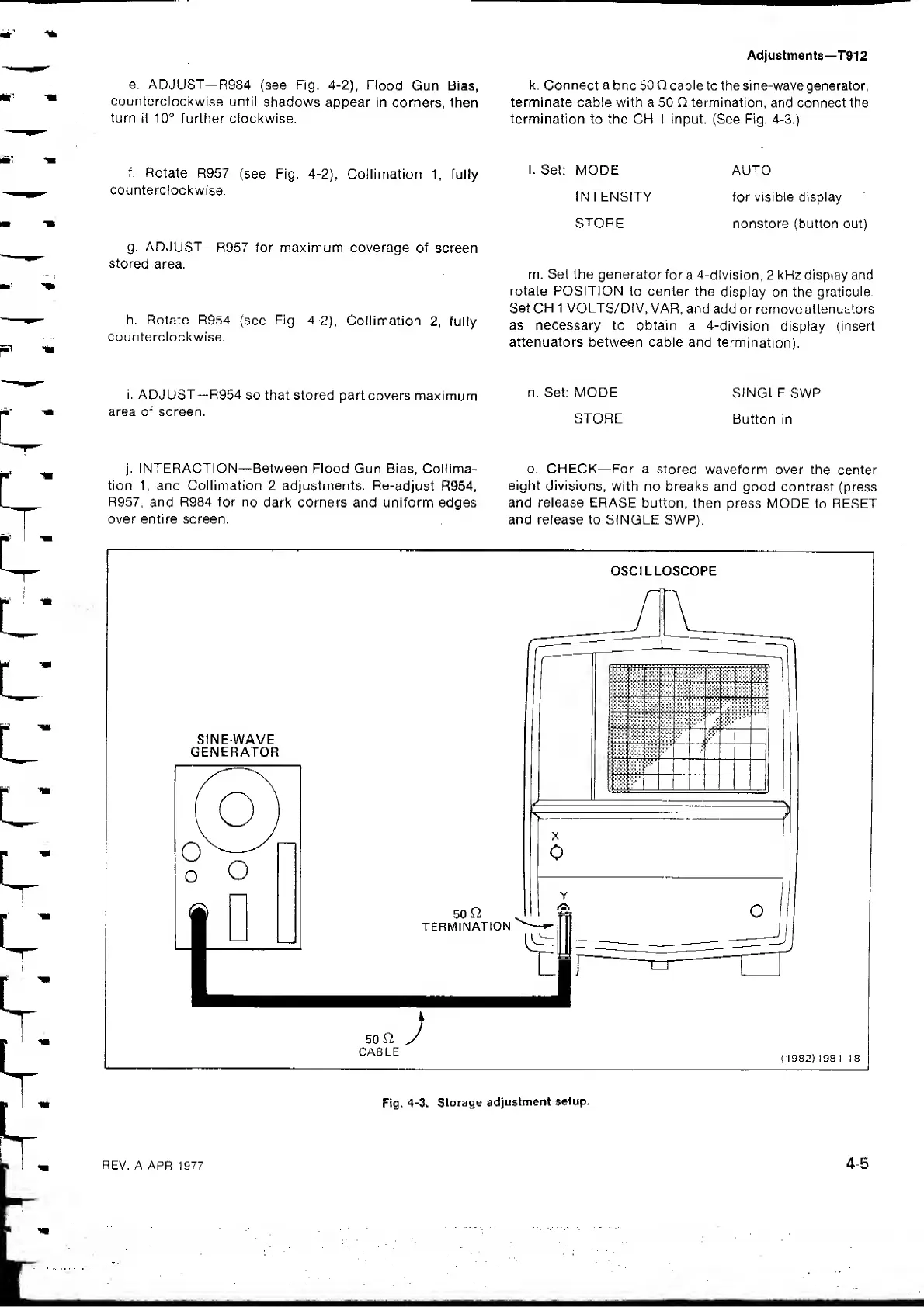
k.
Connect
a
bnc 50
C
cable
to the sine-wave generator,
terminate cable with a
50
O termination,
and connect the
termination
to the CH 1 input. (See Fig. 4-3.)
I.
Set: MODE AUTO
INTENSITY for visible display
STORE
nonstore (button out)
m. Set the generator for
a 4-division, 2 kFIz display and
rotate POSITION
to center the
display on the
graticule.
Set
CH
1 VOLTS/DIV,
VAR, and add
or
remove
attenuators
as necessary to obtain a
4-division display (insert
attenuators between cable and
termination),
n.
Set:
MODE
SINGLE
SWP
STORE
Button in
o. CHECK—For a
stored
waveform over the
center
eight
divisions,
with no breaks and
good contrast (press
and release ERASE
button, then press
MODE
to RESET
and release to SINGLE
SWR).
OSCILLOSCOPE
50
CABLE
;
(
1982
)
1981-18
Fig.
4-3. Storage
adjustment
setup.
 Loading...