Performance Verification
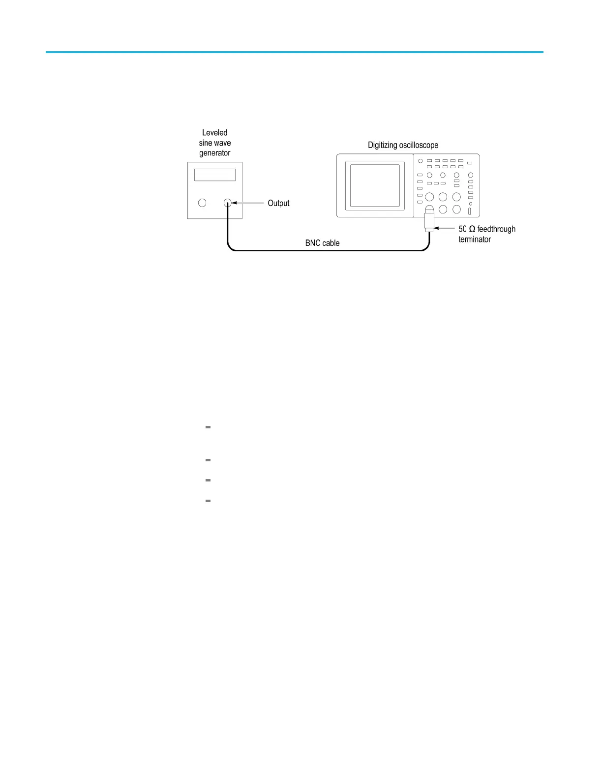
2. Connect th e osc
illoscope channel under test to the leveled sine wave generator
as shown in the following figure:
3. Set the osc
illoscope Vertical Scale (volts/division) to 500 mV/div.
4. Set the oscilloscope Horizontal Scale (seconds/division) to 25 ns/div.
5. Set the leveled sine wave generator frequency to 10 MHz.
6. Set the leveled s ine wave generator output level to approximately 500 mV
p-p
so that the measured am plitude is approximately 500 mV.(Themeasured
amplitude can fluctuate around 500 mV.)
7. Push Set To 5 0%. Adjust Trigge r Level as necessary and then c heck that
triggering is stable.
8. Set the levele d sine wave g ene rator frequency to:
100 MH z if you are checking a TBS1154, TBS1152, TBS1104, or a
TBS1102
60 MHz if you are checking a TBS1064 or TBS1062
40 MHz if you are checking a TBS1042
25 MHz if you are checking a TBS1022
9. Se
t the oscilloscope Horizontal Scale (seconds/division) to 5ns/div.
10. Set the leveled sine wave generator output level to approximately 750 mV
p-p
so that the measured amplitude is approximately 750 mV.(Themeasured
amplitude can fluctuate around 750 mV.)
1
1.
P
ush Set To 50%. Adjust Trigger Level as necessary and then check that
triggering is stable.
12. For the TBS1154 and TBS1152 models, s et the frequency to 150 MHz, and
increase the amplitude to 1 V
p-p
. Verify stable triggering.
13. Set the oscilloscope Horizontal Scale (seconds/division) to 2.5 ns/div.
14. Change the o scilloscope setup using the following table:
4–8 TBS1000 Series O scilloscope Service Manual

 Loading...