TDS2CM Communications Module
TDS 200-Series Extension Module Instructions
15
Testing the RS-232 Interface
To test the oscilloscope RS-232 interface:
1. Connect the oscilloscope to a personal computer (PC) using an
appropriate RS-232 cable (refer to the table on page 12).
2. Turn on the PC.
3. On the PC, run a terminal-emulator program such as the
Microsoft Windows Terminal. Make sure the PC serial port is set
as follows:
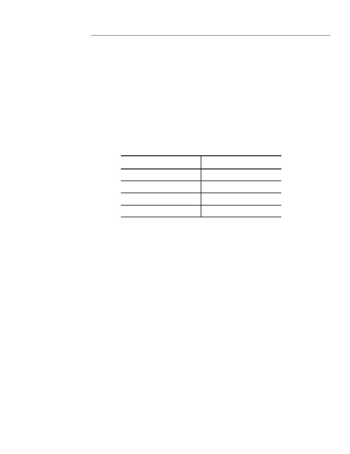
Function Setting
Baud rate
9600
Data flow control Hardflag
Parity None
EOL string LF
4. Turn on the oscilloscope.
5. Connect the oscilloscope probe to the channel 1 input connector.
Attach the probe tip and ground lead to the PROBE COMP
connectors.
The PROBE COMP signal is a square wave with a frequency
of ≈1 kHz and a peak voltage of ≈5 V. The following figure
shows how to hook up the probe to the oscilloscope.

 Loading...


