Getting Acquain
ted With Your Instrument
Connecting Signals. When connecting audio signals to the Analog Input connector, you can use either balanced or
unbalanced sig
nals. If you connect unbalanced signals to the inputs, you do not have to g round the unused lead (grounding
the unused lead can reduce noise).
When connecting the Analog Output connectors, you can connect them as balanced or unbalanced. However, if you connect
the balanced outputs to an unbalanced input, you must ground the unused lead. You can ground either lead.
NOTE. Note th
at grounding the unused lead does not attenuate the output but it does halve the clipping level. Therefore,
you must attenuate the output by at least 6 dB to avoid clipping. The output signal level in unbalanced mode is double
the signal level in balanced mode.
Units that h
ave both analog and digital capability can have AES or embedded inputs converted to analog and then routed to
the s ix balanced outputs. Embedded audio can be output to the AE S B connector (when it is configured as an output). AES
A can also be routed to the AES B connector. Decoded Do lby can also be routed to the analog output connector.
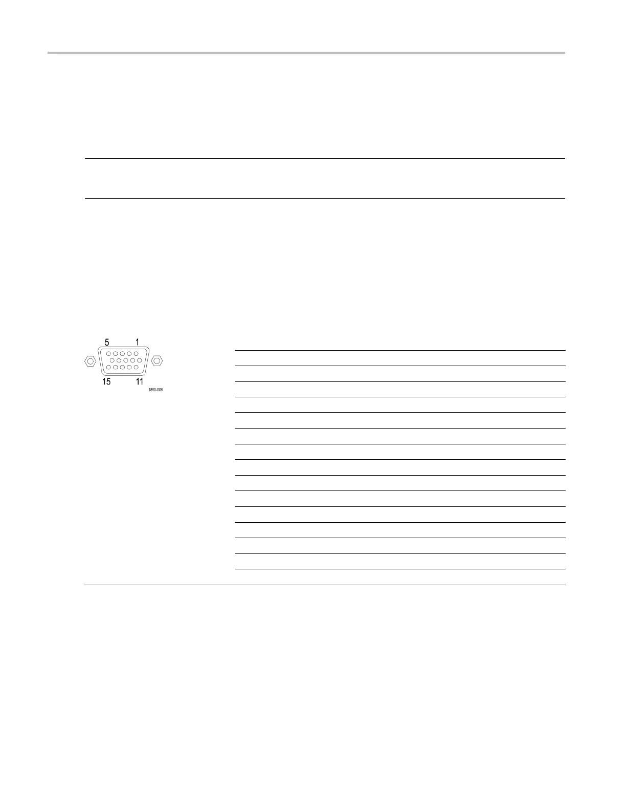
EXT DISPLA
Y Connector Pin Assignment
This is the display output. The display resolution is 1024 x 768. The output is compatible with standard analog PC monitors,
either CRT or LCD-based. The EXT DISPLAY connector is a 15-pin D-type connector w ith socket contacts.
Pin Pin name
1 Red Video
2
Green Video
3 Blue Video
4 Not connected
5
Ground
6
Red Ground
7
Green Ground
8
Blue Ground
9
+5 V (for monitor EEP RO M)
10
Not Connected
11
Not Connected
12 ID Bit
13
Horizontal Sync
14
Vertical Sync
15
ID Clock
16 Waveform Monitors Quick Start User Manual
 Loading...


