Application Exa
mple
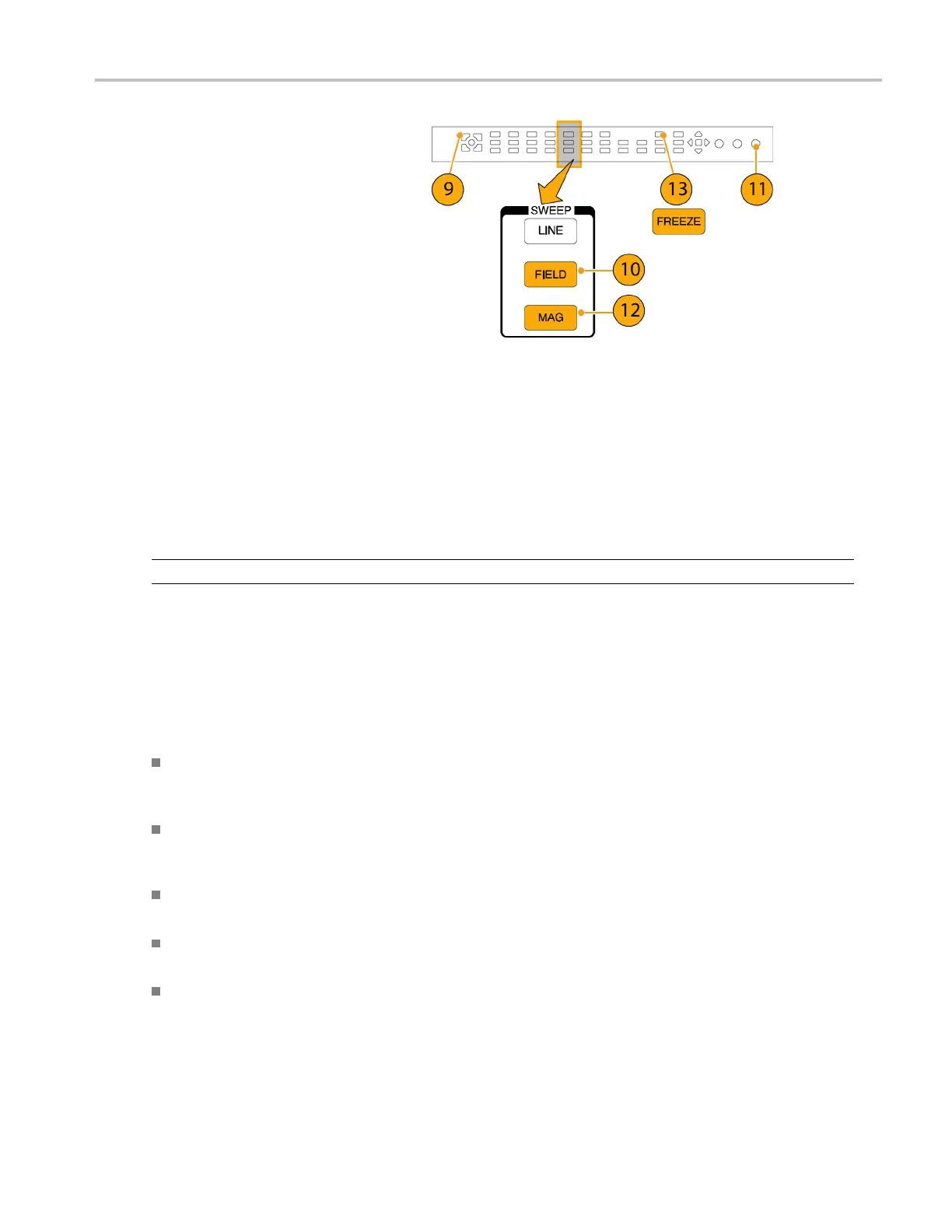
9. Select a second tile.
10. Press the FIELD button to put a
second tile in field mode and choose an
appropriate wa
veform mode.
11. Use the HORIZON
TAL knob to center
the vertical interval.
12. Press the MAG button to increase the
timing resolution.
13. Press the FREEZE buttontosavethe
waveform as a b
aseline.
14. Apply an input that needs to match timing
of the first in
put.
15. Adjust the ti
ming offset of the signal
being timed to match the timing to the
saved baseline.
16. Repeat steps 14 and 15 for any other
required sig
nals.
NOTE. Use the Cursors as markers or to measure timing differences between sources.
Other tiles can be used to set fine timing and check color frame alignment on composite signals. Alternatively, the other two
tiles coul
d be used for line and field rate displays without Mag active to show the location of significantly mistimed signals.
Using the Timing-Display Method
The Tektronix Timing Display provides a quick, easy way to measure the timing of an input relative to the external reference:
The rectangular display automatically scales to match the input signal. For progressive signals, the display represents
one field; for interlace signals, the display represents one frame; and for composite inputs, the d isplay represents one
color frame.
The cross-hair in the center represents zero offset, and the circle represents the timing of the input signal. Lines of
advance or delay are shown as vertical displacement, while timing errors of less than one line are shown as horizontal
displacement. If the input is at the same time as the reference, then the circle will be centered on the cross-hair.
The timing offset is also shown numerically as lines and micro-seconds of advance or delay in the boxes at the right
side of the display.
For input and reference signals with closely related frame rates, there is only one timing relationship, so a single circle is
shown on the display to indicate the timing offset of the input signal.
For input and reference combinations with more complex relationships, multiple circles are displayed to indicate all the
possible interpretations of the timing offset, with the one that is closest to zero s hown with emphasis. The numerical
readouts will correspond to the timing indicator circle with the emphasis.
Waveform Rasterizers Quick Start User Manual 119
 Loading...


