Application Exa
mple
The Relative to: box indicates the chosen zero point for the timing display. The default is Rear Panel. In this mode,
the offset is ze
ro when the input and reference are at the same timing at the rear panel of your instrument. The other
choice is Saved Offset. In this mode, you can save the timing from one signal and then display the timing relative to
that saved offset.
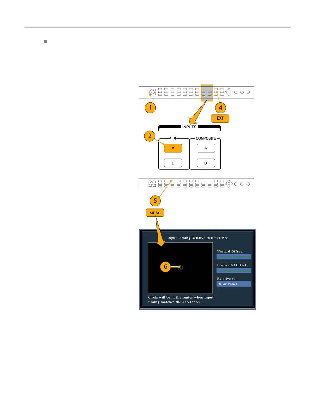
To Use the Timi
ng Display to Time a Signal to a Reference.
1. Selectatileinwhichtotimetheactive
input.
2. Apply the input signal to be timed
to the approp
riate input, terminate it
properly, and select it. (See page 9, Line
Term ina t io n .)
3. Apply the house reference signal to the
external re
ference input, terminating it
properly.
4. Press the EX T button to select External
Reference mode.
5. Press the
MEAS button to select the
Timing display for the tile selected in
step 1.
6. If only one circle is displayed, adjust
the timin
g offset of the black generator
to match the timing to the external
reference. Adjust for a perfect
coincid
ence of the circle around the
reference target (circle turns green at
coincidence) and null values of the
vertic
al and horizontal timing readouts.
7. If mult
iple circles a re displayed, the
timing is complex, and you must choose
the one you want. The measurement that
is clos
est to zero offset is displayed with
emphasis and appears in the readouts.
NOTE. See Timing Displays for Simple
Versus
Complex Timing in the WVR6020,
WVR7020, and WVR7120 User Technical
Reference on the User Documentation CD
that c
ame with your instrument for m ore
information about complex timing displays
and their elements.
8. Repea
t s tep 6 or 7 for any other signals.
120 Waveform Rasterizers Quick Start User Manual
 Loading...


