Installation
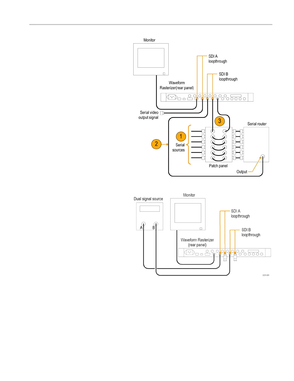
For monitoring
serial digital
signals around a routing switcher
1. Connect your serial sources through a
patch panel to a serial router.
2. Connect the output of the serial router to
a SDI loop-through input for comparison.
3. Connect the other SDI loop-through
input to the patch panel to jumper the
signal that you want to compare to signal
connectedinstep2.
For monitoring dual link signals
NOTE. This setup requires that Option DL
be installed on y our instrument.
1. Connect the A and B outputs from your
dual link signal source to the two inputs
on this instrument.
2. Terminate the loop-throughs on this
instrument with 75 Ω terminators.
NOTE. See the Specifications and
Performance Verification manual on the User
Documentation CD for maximum allowable
cable lengths.
Line Termination
Your instrument uses passive loop-through, serial and analog video inputs. Accordingly, the loop-through input must
be terminated externally. The passive loop-through capability of the inputs provides the benefit o f a signal path that is
uninterrupted by input selection, power interruption, and even most internal faults. In addition, this instrument directly
monitors the actual signal traveling to downstream equipment rather than providing a retransmitted signal or requiring a
duplicate input signal.
Waveform Rasterizers Quick Start User Manual 9
 Loading...


