base station degrade the wireless signal. Place the antenna above ground level and direct it towards the nearest
base station.
• Antennas are affected by the density of materials, so place them away from walls, metal screens, mirrors, etc.
• Do not place the antenna near columns; these might throw shadows and reduce the coverage area.
• Keep the antenna away from metal pipes such as canalization, air-conditioning, etc.
• Bear in mind that other wireless devices such as telephones, microwaves, etc., can temporarily interfere with the
quality of the wireless signal.
• Installing antennas in racks alongside communication devices, computers, etc., is not recommended. Use an ex-
tension cable and place the antenna outside.
The following recommendations are applicable to all wireless devices:
• Do not touch or move the antenna while the device is transmitting or receiving.
• When the antenna is transmitting, do not touch equipment containing devices that radiate very close to, or touch-
ing, any exposed part of the body (particularly the face and eyes).
• Do not install the device in areas where the atmosphere is potentially explosive.
• Wireless devices can cause interference in other devices. Do not use them in areas where medical equipment is
installed.
3.5.3 Connecting the WLAN antenna
The Teldat H2 RAIL is fitted with type N connectors to connect up to two WLAN (Wi-Fi) antennas (on models
equipped with this interface).
Since the router doesn't have any internal antennas, external antennas must be installed on the Teldat H2 RAIL to
improve WLAN signal quality.
The cable used to connect the antennas must be valid for RF signal communications of up to 2.4 GHz (5.7 GHz for
802.11a) frequencies and impedances of 50 Ohm. Please note, the quality and length of an antenna cable can affect
the quality of RF signals transmitted and received. This, in turn, will affect the device coverage and data exchange
rates.
Please note, an appropriate software license must be installed for the WLAN interface to work.
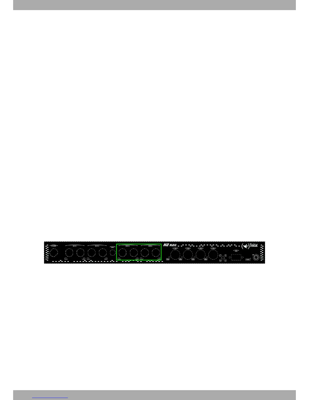
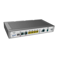
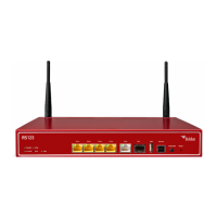
The following image shows the location of the WLAN antenna connectors (MOD3 and MOD4).
Fig. 11: WLAN antenna connectors
For further information on WLAN interfaces, please see the Teldat-Dm771-I Wireless LAN Interface manual.
3.5.4 Connecting the GPS antenna
The Teldat H2 RAIL has an FME connector to connect an active GPS antenna (on models equipped with this inter-
face).
Since the router doesn't have any internal antennas, an active 3.3V external antenna must be installed on the Teldat
H2 RAIL to optimize the GPS signal quality.
The cable used to connect the antennas must be valid for radio frequency (RF) signal communications of up to 1.5
GHz frequencies and impedances of 50 Ohm. Please note the quality and length of an antenna cable can affect the
quality of the RF signals transmitted and received. This, in turn, will affect the device coverage and data exchange
rates.
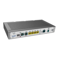
The following image shows the location of the GPS antenna connector.
3 Components and power supply Teldat S.A.
12 Teldat H2 RAIL