Chapter 3 Components and power supply
This chapter describes the Teldat H2 RAIL chassis and its main components. The following sections are included:
• Components.
• Assembly instructions.
• Power supply.
• RESET button.
• Data connection.
• SIM card installation.
3.1 Components
3.1.1 Front panel
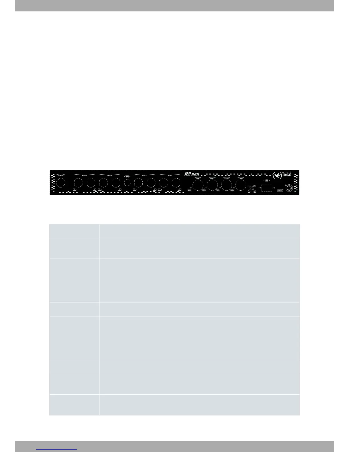
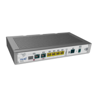
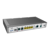
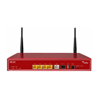
The following image shows the device's front panel.
Fig. 2: Front panel
The front panel elements are as follows:
Table 1: Front panel elements
Item Description
POWER Power connection. For further information on the power connection, please see Power
source on page 7
MOD1, MOD2 WWAN/WLAN antenna connectors.
The created interface is cellular1/x or wlan1/0 for MOD 1, and cellular2/x or wlan2/0 for
MOD2.
The type of device installed for each position depends on the commercial configuration.
GPS GPS antenna connector.
MOD3, MOD4 WWAN/WLAN antenna connectors.
The created interface is cellular3/x or wlan3/0 for MOD 3, and cellular4/x or wlan4/0 for
MOD4.
The type of device installed for each position depends on the commercial configuration.
LAN1..LAN4 LAN connectors for 4-port Gigabit Ethernet switch.
AUX DB9 connector, which provides access to the device's local console for configuration and
monitoring purposes.
RESET Reset button. For further information on how the reset button works, please see RESET but-
ton on page 9
In addition to the connectors, the front panel also contains a set of LEDs that indicate router status.
3 Components and power supply Teldat S.A.
4 Teldat H2 RAIL