TS4000 Radio Modem User’s Manual Appendix F – Internal Jumper Block 97
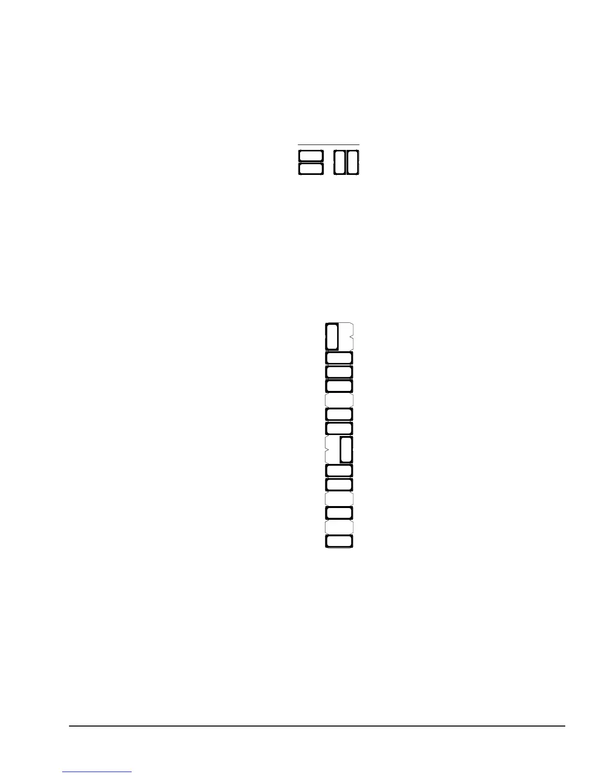
To enable power on pin 9 (RI - Ring Indicator) of serial port 2, locate the jumpers
across pins 23 and 24, and pins 25 and 26. Remove these two jumpers using
the small needle-nose pliers or tweezers and reinstall the jumpers across pins 23
and 25, and pins 24 and 26, as shown below.
Jumper Settings for
Power on Serial Port 2
- Pin 9
Port 2 - Pin 9
RI Signal
Jumpers
Open
(default)
Modem
Power
25
23
26
24
25
23
26
24
To enable TTL levels for serial port 1 move the following jumpers as shown
below.
Jumper Settings for
TTL Levels on Serial
Port 1
Move the jumper across pins 2 and 4 to pins 1 and 2.
Move the jumper across pins 5 and 7 to pins 5 and 6.
Move the jumper across pins 8 and 10 to pins 9 and 10.
Move the jumper across pins 12 and 14 to pins 11 and 12.
Port 1 DTR RS232/TTL signal
1
3
5
7
9
11
13
15
25
27
29
17
19
21
23
31
2
4
6
8
10
12
14
16
26
28
30
18
20
22
24
32 CPU I/O
Port 2 DSR 1k pullup
Port 2 DSR pin
Port 2 RI pinPort 2 RI pin
DC power
DC powerDC power
DC power
Port 2 DSR RS232 signal
Port 1 DSR TTL signal
Port 1 RI pin
Port 1 DTR pinPort 1 DTR pin
Port 1 RI pin
Port 1 DSR RS232 signal
Port 1 CTS TTL signal
Port 1 RD TTL signal
Port 1 DSR RS232 signal
Port 1 DSR pin
Port 1 DSR 1k pullup
Port 1 DCD TTL signal
Port 1 CTS RS232 signal
Port 1 CTS pin
Port 1 RD pin
Port 1 RD RS232 signal
Port 1 DSR TTL signal
Port 1 DCD RS232 signal
Port 1 DCD pin
Ground
(spare)
TS4000 Jumper Block
Serial Port 1 TTL Level Settings


 To Next Page