SECTION
573-118-700TC
CONTENTS
Noninterfering
BLANK
Tape
Feed
Out
Mechanism
PAGE
Artnature
hinge . • • • • • • • • • • • • • • 164
Armature
locklever
spring
• • • • • • • 169
Armature
spring
. . • • • • • • • • • • • • 164
Contacting
mounting
bracket
. • • • • • 173
Contact
lever
....•
·•
. • • . • • • • • • • 173
Contact
lever
spring.
. . . • • . • • • • • 173
Contact
pulse
closure
. • . • . • • • • • • 173
Contact
springs
. . . . • . • • • • • . • • • 172
Drive
arm.
. . . . . . . . . . . . • • • • • • 161
Drive
arm
shaft
rear
bearing.
• • • • • 161
Drive
arm
spring.
. • . • . • • • • • • • • 171
Feed
out
bracket
. • . • • . • • . • • • • • 161
Feed
out pawl . • • . . • • • • • • • • • • • 163
Feed
out pawl
spring
. • • • • • • • • • • 163
Feed
out
switch
. . . • • . • • • • • • • • • 174
Feed
out
switch
(with
pulse
closure).
• 175
Inner
ratchet
check
pawl . • . • • • • • • 167
Inner
ratchet
check
pawl
spring
. • • • 167
Kick-out
arm
. . . . . . • • • • • • • • • • 169
Latch
arm
spring.
. • • • . • . • • • • • • 169
Lifter
lever.
. . . . . . • • • • • • • • • • • 166
Magnet
mounting
bracket
. • • • • • • • • 164
Metering
feed
pawl
spring
. • • • • • • • 166
Noninterfering
clamp
arm
. . • • • • • • 168
Outer
ratchet
check
pawl
spring
. • • • 166
Outer
ratchet
return
spring
. • • • • • • 168
Release
arm
. • . . . . • • . • • • • . • • • 162
Release
arm
latch
. • . • • • • . • • • • • 165
Release
arm
latch
spring.
. • . • . • • • 165
Release
arm
spring
. • • . • • . • • • • • 171
Switch
lever
adjusting
bracket
. • • . • 175
Switch
lever
spring
. . • . • . • • . • • • 174
Tape
length
adjusting
plate.
• • • • . . . 170
Ribbon
Feed
Mechanism
for
Chadless
Tape
and
Fully
Perforated
Tape
Ribbon
feed
drive
arm
spring.
• • • • • 157
Ribbon
feed
eccentric
stud.
. • • • • • • 156
Ribbon
feed
pawl downstop
eccentric
. . • • • . • . • • . • • • • • • • • 157
Ribbon
feed
pawl
spring
. . • • • • • • . 156
Ribbon feed
reversing
arm
spring.
• • 158
Ribbon
ratchet
wheel
spring
washers
..
. . . .
..
. . . . • . • • . • • • . . 157
Ribbon
reversing
plate
. . • • • • . • • • 158
Signal
Bell
Contact
Mechanism
Contact
mounting
bracket.
. • • • • • • . 159
Fw1ction
blade
spring
. • • . • • • • • • • 159
Page 6
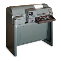
1. GENERAL
1.
01
This
section
contains
the
specific
re-
quirements
and
adjustments
for
the 28
typing
reperforators
and
tape
printers.
1.
02
This
section
has
been
revised
to include
recent
engineering
changes
and
additions,
and
to
rearrange
the
text,
so
as
to
bring
the
sec-
tion
generally
up-to-date.
Since
this
is
an
ex-
tensive
revision,
marginal
arrows
ordinarily
used
to
indicate
changes
have been
omitted.
Note: Remove
power
from
set
or
unit
before
iiiiking
adjustment.
1.
03
Maintenance
procedures
which apply only
to
mechanisms
of a
particular
design,
or
to
certain
models
of 28 typing
reperforators
and
tape
printers
are
so
indicated
in
the
titles
of the
paragraphs
which
contain
these
particular
ad-
justment
requirements.
1.
04
The
adjustments
are
arranged
in
a
se-
quence
that
should
be followed
if
a
com-
plete
readjustment
of
the
unit
were
undertaken.
The
tools
and
spring
scales
required
to
perform
these
adjustments
are
listed
in
the
applicable
section.
After
an
adjustment
is
completed,
be
sure
to tighten any
nuts
or
screws
that
are
loosened.
The
adjusting
illustrations
indicate
tolerances,
positions
of moving
parts,
spring
tensions
and the
angles
at
which
scales
should
be
applied when
measuring
spring
tensions.
If
a
part
mounted on
shims
is
removed,
the
number
of
shims
used
at
each
of
its
mounting
screws
should be noted
so
that
the
same
number
is
re-
placed
when the
part
is
remounted.
1.
05
After
a few
weeks
(300
to
500
hours)
of
operation
of a
new
unit, the
unit
should
be
re
lubricated
to
make
sure
all
operating
points
have been
properly
lubricated.
1.
06
Recheck
all
clutch
gaps
to
insure
that
the
parts,
after
seating
themselves,
have
not
caused
the
clutch
gaps
to open
up.
Reset
if
nec-
essary.
Standard
readjustment
periods
are
to
be
maintained
thereafter.
1.
07
Reference
made
to
left
or
right,
up
or
down,
front
or
rear,
etc,
apply
to
the
unit
in
its
normal
operating
position
as
viewed
from
the
front.
..
''·)
..
)
.)
.)
·~)