AIRMAN 8+ Maintenance | en 21
Bosch Security Systems, LLC
Customer Maintenance Manual
2024-11 | 07 | F.01U.387.060
5.5 ANR troubleshooting
Notice!
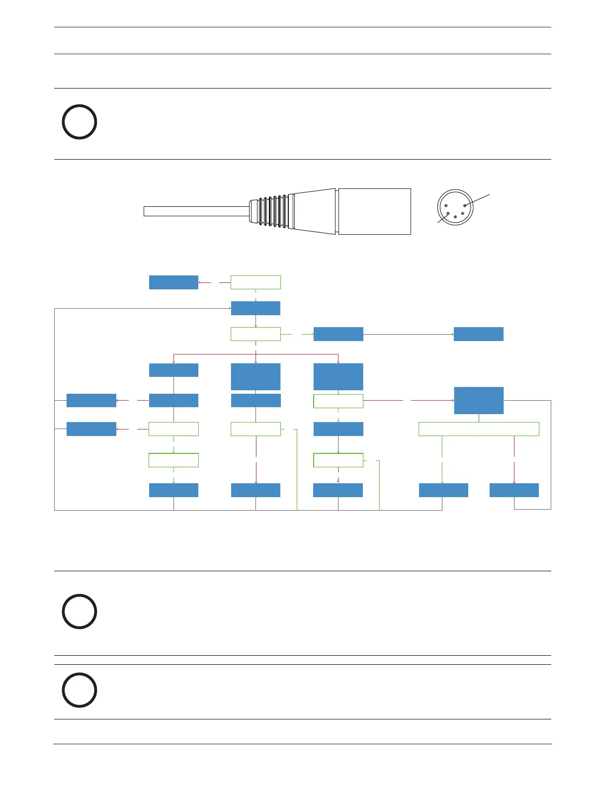
The ANR circuits must be powered to perform testing. For the Airman8P-0210, -211, and
0214, connect the headset to the microphone test circuit shown in section 5.3.2. The ANR
circuitry for the Airman8P-0212 requires power to be applied to XLR pin #5 for the ANR to
function. For this test, apply 12 to 28 VDC to pin #5. Connect ground to pin #2.
1
Pin 2
Ground
3
4
Pin 5
+8 - 28 VDC
Figure5.4: Airman8P-0214 ANR Wiring Note
Troublehoot
the speakers
ANR does not work
at all
ANR does not work
on the boom side
but does on the
non-boom side
ANR does not work
on the non-boom
side but does on the
boom side
Check overhead cable
and solder connections
on both boom and
non-boom sides
Turn the power and
ANR on
Adjust the ANR
Replace
Boomside PCBA
Replace
non-boomside PCBA
Replace
non-boomside PCBA
Repair or replace
the cable
No
NoNo
No
Repair the connections
or replace the cable
No
Replace boom side
PCBA
No
No
Does audio pass
with no power?
Does ANR work
on both sides?
Does the ANR work on
the non-boom sides?
Task complete
Yes
Yes
Yes
Yes
Yes
Yes
Yes
Yes
Adjust the ANR
Adjust the ANR
Adjust the ANR
Are there voltages
at J11 and J12?
Check main cable
connections
No
Does the ANR work
on the boom sides?
Are the overhead cable
connections good?
Are the main cable
connections good?
Are there voltages at J11
and J12 on both sides?
Figure5.5: ANR Troubleshooting
5.5.1 Measuring ANR circuit voltages and switch function
Notice!
This headset was designed, tested, and approved to FAA TSO C139a. The TSO requires the
headset meet the minimum performance specifications as defined in RTCA DO-214A. This
document and specifications listed here reference the test procedures, product settings,
and equipment used as defined in these standards. Refer to the standard for details on how
to perform individual tests.
Notice!
Minimum attenuation requirements are not requirements of FAA TSO. To achieve the
maximum attenuation, Bosch approved test system is required.
To measure voltage and switch function on the boom side, do the following: