42 en | Wiring Diagrams and Connectors AIRMAN 8+
2024-11 | 07 | F.01U.387.060
Customer Maintenance Manual
Bosch Security Systems, LLC
8 Wiring Diagrams and Connectors
Airman 8+ Series headsets are available with multiple connector styles depending on the
application of use. All models utilize custom cables developed specifically for cockpit use.
All connection points implement strain and bend relief features to provide long-term
durability. Shielded wire throughout the headset protects against RFI (Radio Frequency
Interference) and EMI (Electromagnetic Interference).
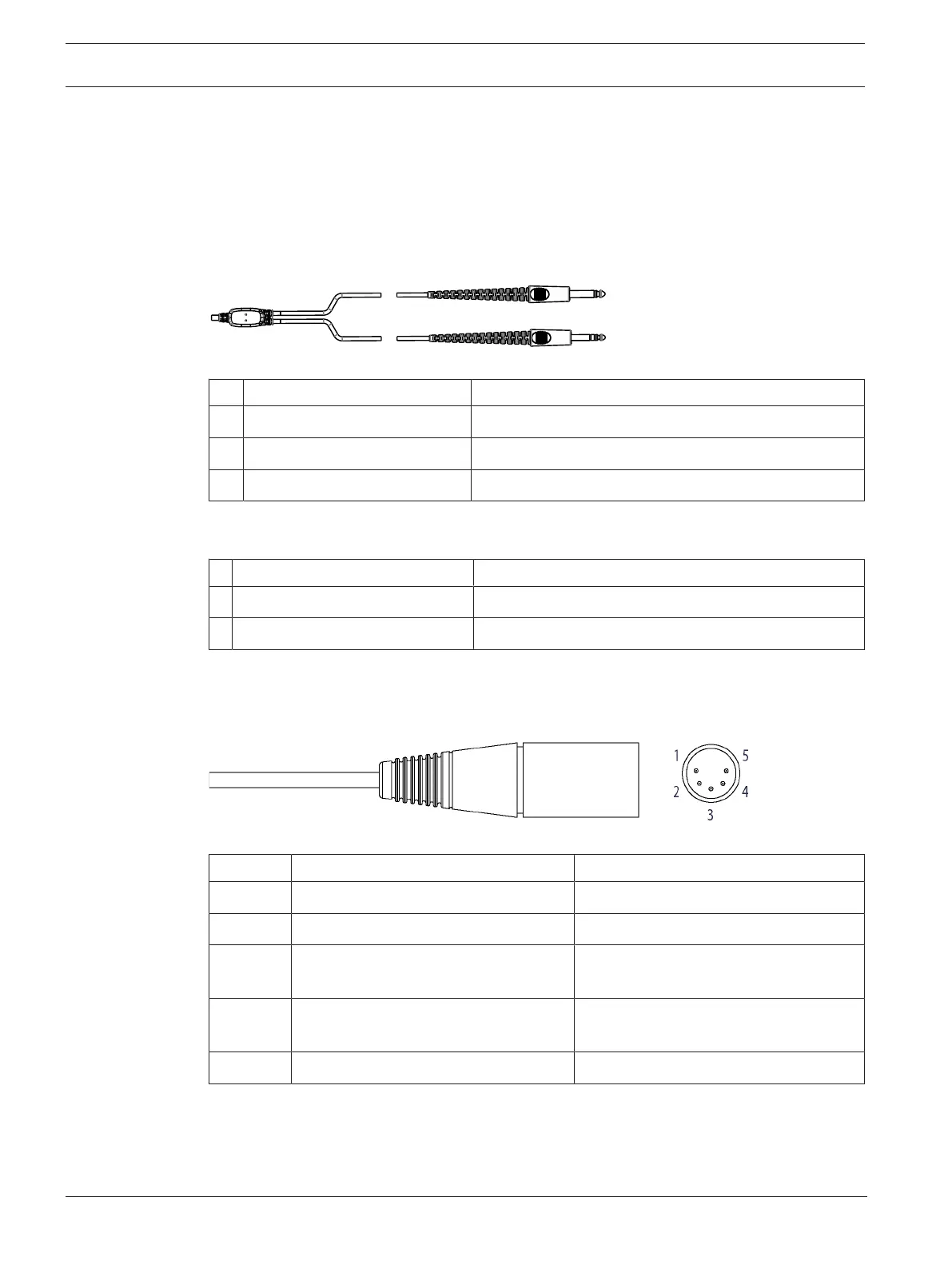
PJ-068 / PJ-055 Connector Diagram for Airman8P-0210
Figure8.1: PJ Connector
1 PJ-068 or equivalent Description
Tip Not Used
Ring Mic Signal (ANR Power +)
Sleeve Mic GND (ANR Power -)
Table8.1: PJ-055, Mic Plug Connections
2 PJ-055 or equivalent Description
Tip Headphone Signal
Sleeve Headphone GND
Table8.2: PJ-055, Headphone Plug Connections
5-Pin XLR Aircraft Cable
Figure8.2: 5-pin XLR Connector
Pin Description Color
1 Headphone Signal Yellow
2 Headphone GND Shield or Drain + Black
3 Mic Power and Signal
(ANR Power +)
White
4 Mic Power and Signal
(ANR Power -)
Shield or Drain + Blue
5 ANR Power Red
Table8.3: 5-pin XLR Wiring Airman8P-0211