AIRMAN 8+ Wiring Diagrams and Connectors | en 43
Bosch Security Systems, LLC
Customer Maintenance Manual
2024-11 | 07 | F.01U.387.060
Pin Description Color
1 Headphone Signal Yellow
2 Headphone GND
(-0214 ANR Power-, see note)
Black
3 Mic Power and Signal
(-0214 ANR Power+, see note)
White
4 Mic Power and Signal
(-0214 ANR Power-, see note)
Shield or Drain + Blue
5 ANR Power+ Red
Table8.4: 5-pin XLR Wiring Airman8P-0212, -0214
Notice!
For -0214, if pin 5 power is not available, ANR will be powered by mic power and the GND
pins (2 and 4) are tied together.
Notice!
The Airman 8+ automatically uses power from pin 5, if it is provided by the aircraft.
The Airman8P-0212 MUST have power on pin 5 for ANR to function. If pin 5 power is not
available, use the AIRMAN8P-0211 or AIRMAN8P-0214 version for ANR functionality.
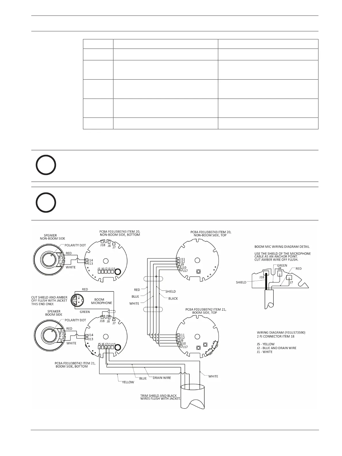
Figure8.3: Airman 8P-0210 Wiring Diagram