LE910C1 Hardware User Guide
1VV0301298 Rev. 1.08 - 2017-11-14
Reproduction forbidden without written authorization by Telit Communications S.p.A. - All Rights Reserved
Telit Confidential Information, provided under NDA Page
74 of 119
8.4.1. Modem Serial Port 1 Signals
Serial Port 1 on LE910C1 is a +1.8V UART with 7 RS232 signals. It differs from the PC-RS232 in signal
polarity (RS232 is reversed) and levels.
Table 25 lists the signals of LE910C1 Serial Port 1.
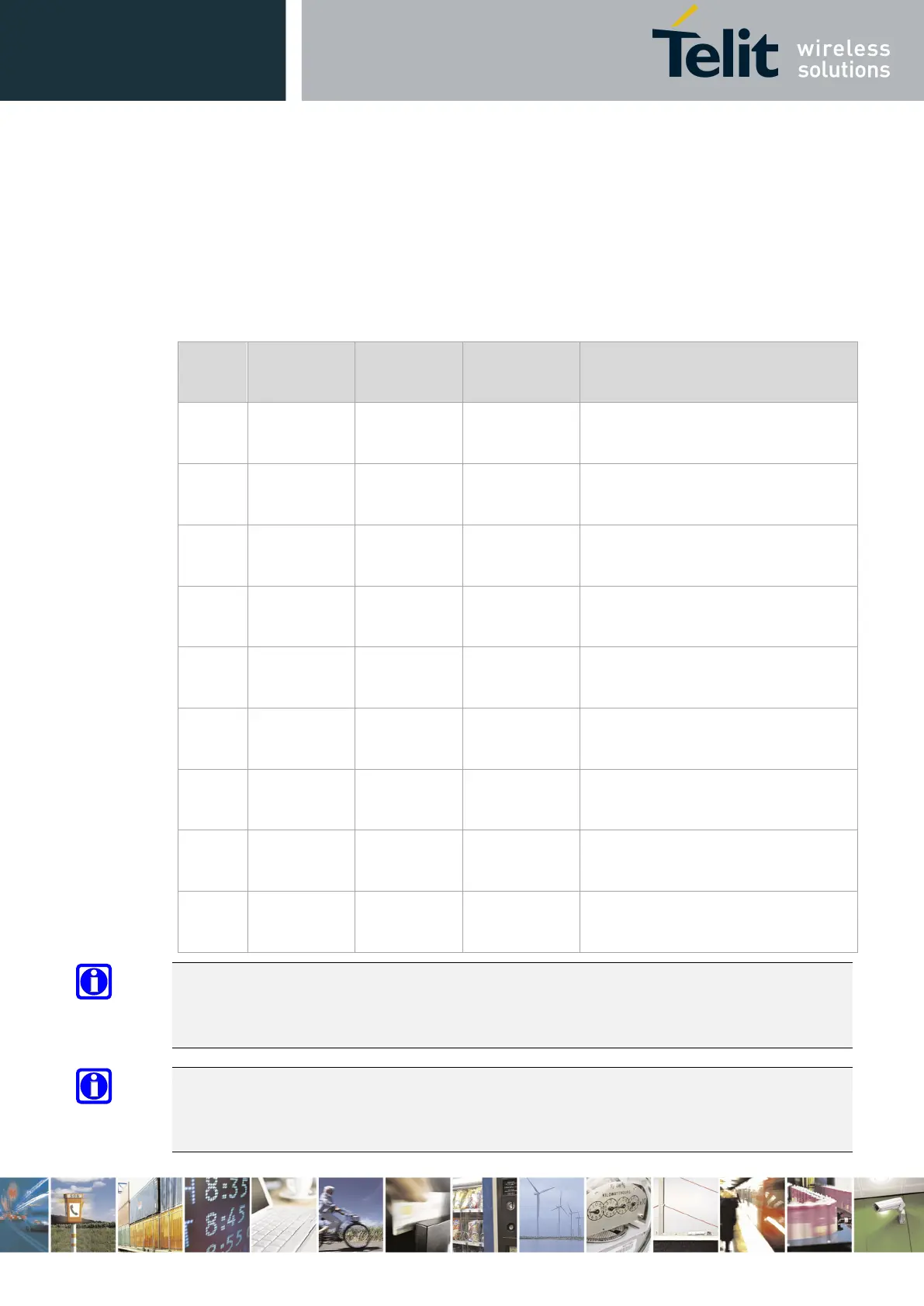
Table 25: Modem Serial Port 1 Signals
RS232
Pin No.
Signal LE910C1
Pad No.
Name Usage
1 DCD -
DCD_UART
N14 Data Carrier
Detect
Output from the LE910C1 that
indicates carrier presence
2 RXD -
TX_UART
M15 Transmit line
*see Note
Output transmit line of the LE910C1
UART
3 TXD -
RX_UART
N15 Receive line
*see Note
Input receive line of the LE910C1
UART
4 DTR -
DTR_UART
M14 Data Terminal
Ready
Input to LE910C1
DTE READY condition
5 GND A2, B13,
D4…
Ground Ground
6 DSR -
DSR_UART
P14 Data Set
Ready
Output from the LE910C1 that
indicates that the module is ready
7 RTS -
RTS_UART
L14 Request to
Send
Input to LE910C1 controlling the
Hardware flow control
8 CTS -
CTS_UART
P15 Clear to Send Output from LE910C1 controlling the
Hardware flow control
9 RI - RI_UART R14 Ring Indicator Output from LE910C1 indicating the
Incoming call condition
NOTE:
DCD, DTR, DSR, RI signals that are not used for UART functions can be configured as GPIO using AT
commands.
NOTE:
To avoid a back-
powering effect, it is recommended to avoid having any HIGH logic level signal
applied to the digital pins of the module when it is powered OFF or during an ON/OFF transition.
 Loading...


