1VV0301078 Rev.10 – 2015-11-11
Reproduction forbidden without written authorization from Telit Communications S.p.A. - All Rights Reserved. Page 22 of 88
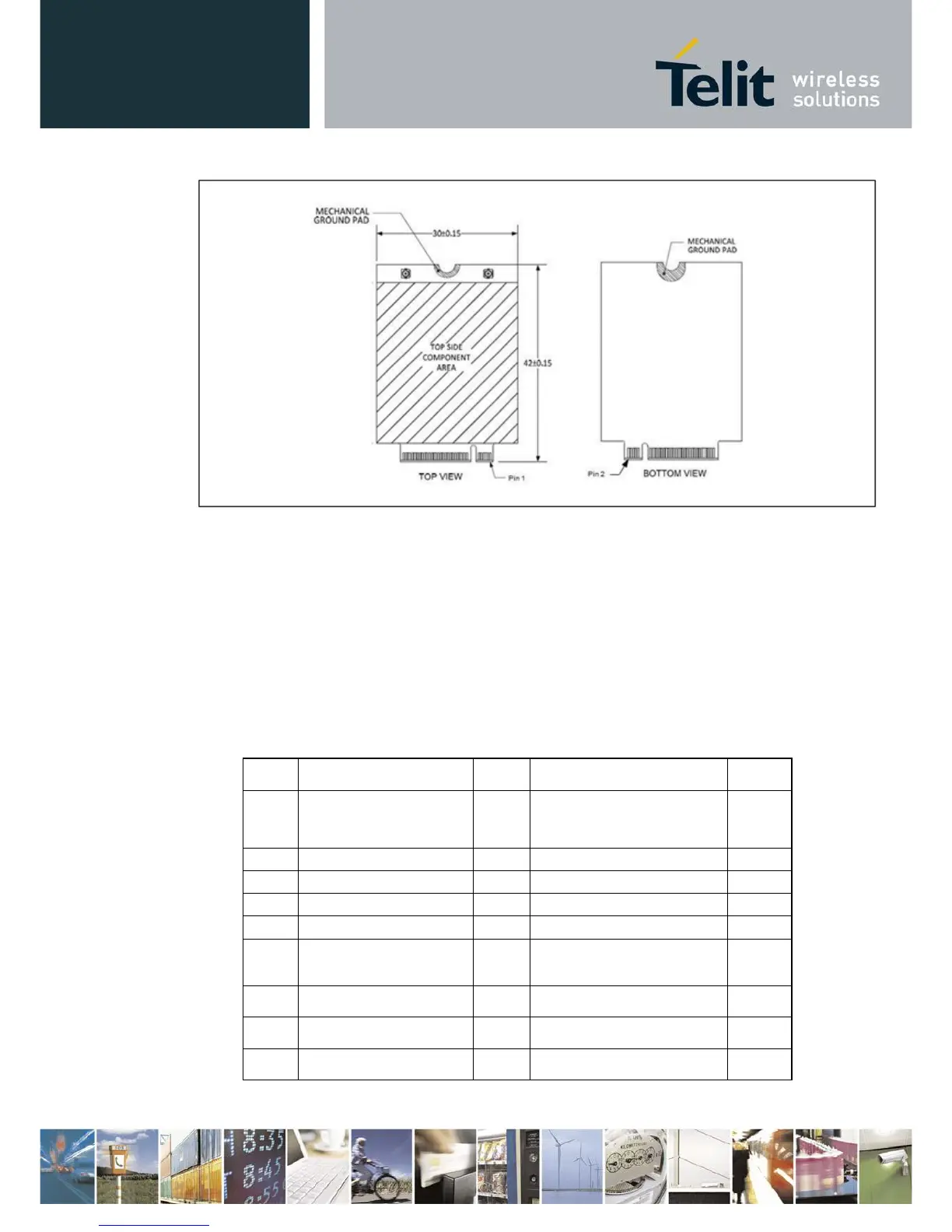
Figure 5 PCI Express M.2 Module Interface
A complete description of all interface signals available at the host interface is listed in Table
4. Some features, such as GNSS and Antenna Tuning, are not available on every M.2 module.
On those modules, the signals at the application interface are not connected on the M.2
module.
Table 4
M.2 Host Interface Signals