18
maximum range of the meter, “OL” will show on
the display.
• When measuring in-circuit resistance, all of the
power within the measured circuit must be shut
off before measurement and all of the capacitors
must be discharged to ensure a correct
measurement.
• When measuring low resistance, the test lead will
bring about measurement errors of resistance
between 0.10 and 0.20Ω. To obtain accurate
readings, relative measurement can be adopted.
• Firstly, short the input test lead, then press the
MENU button and press F2 to enter the relative
measurement.
• Carry out the measurement of low resistance after
the meter has automatically subtracted the display value of the shorted test lead.
• If the resistance value is greater than 0.50Ω for a shorted test lead, the test lead
should be checked to see if any are loose.
• When measuring resistance above 1MΩ, the readings require a few seconds to
stabilise. It is normal for measurement of high resistance. In order to obtain stable
readings, short test lines can be used for the measurement.
• Do not input a voltage higher than 30V in AC (rms), AC (peak 42V) or 60V in DC to
avoid personal injury.
• After completing all of the measuring operations, disconnect the connection
between the test leads and the circuit under test.
CONDUCTANCE
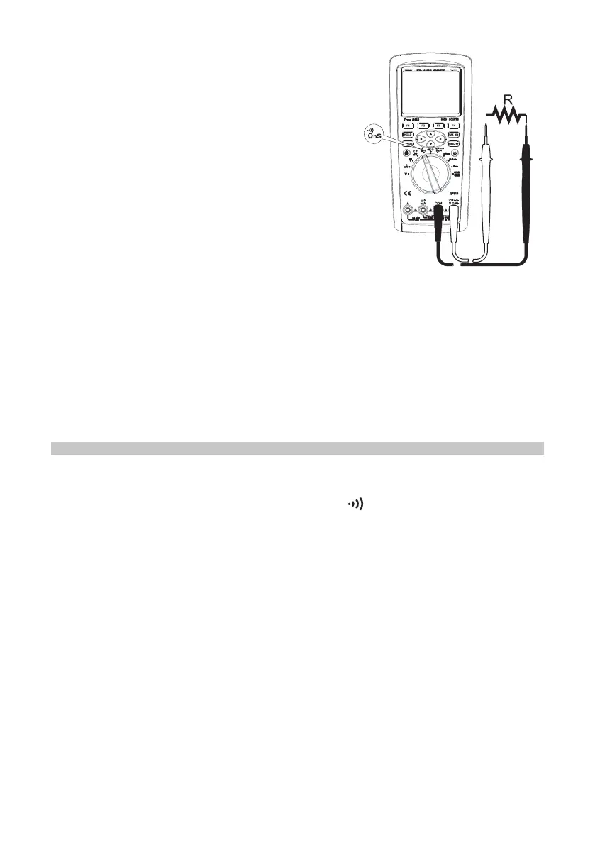
• Insert the red test lead into the Ω terminal and the black test lead into the COM
terminal.
• Set the rotary switch to the measurement Ω nS . Press the SELECT button to
select conductance measurement 60nS.
• Connect the test leads to both ends of the measured resistance.
• Directly read the measured conductance value on the display.
Warnings
• When measuring the in-circuit resistance, all of the power within the measured
circuit must be shut off before measurement and all of the capacitors must be
discharged to ensure the correct measurement.
• Do not input a voltage higher than 30VAC (rms), AC (peak 42V) or 60V DC in
order to avoid personal injury.
• After completing all the measuring operations, disconnect the connection between
the test leads and the circuit under test.


 To Next Page