19
CAPACITANCE
CONTINUITY TEST
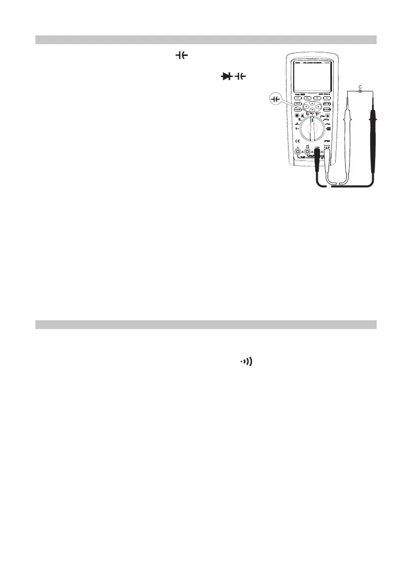
• Insert the red test lead into the terminal and the
black test lead into the COM terminal.
• Set the rotary switch to the measurement and
press the SELECT button to select capacitance
measurement.
• Connect the test leads to both ends of the measured
capacitance (see right).
• Directly read the measured capacitance on the display.
Warnings
• If the measured capacitance shorts or capacitance
value exceeds the maximum range of the meter “OL”
will show on the display.
• For the measurement of capacitance within small
range, relative measurement REL should be adopted to avoid the inuence of
distributed capacitance for correct readings.
• For the measurement of capacitance greater than 600µF, allow for more time to
gain the correct readings.
• To ensure the measuring accuracy, the capacitor should be discharged completely
then put into the meter to measure, especially for a capacitor with high voltage in
order to avoid damage to the meter and personal injury.
• Do not input a voltage higher than 30VAC (rms), AC (peak 42V) or 60V DC in
order to avoid personal injury.
• After completing all of the measuring operations, disconnect the connection
between the test leads and the capacitor under test.
• Insert the red test lead into the Ω terminal and the black test lead into the COM
terminal.
• Set the rotary switch to the measurement Ω nS and press the SELECT button
to enter one of the sub-menu options.
• If pressing the SHORT button, then the buzzer selects short circuit for alarm
sound. If the measured resistance between both ends is <10Ω, the buzzer
continuously sounds. If it is >50Ω the buzzer does not sound.
• When pressing the OPEN button, the buzzer selects open circuit. For the alarm to
sound continuously, the measured resistance between both ends must be >50Ω. If
it is <10Ω, the buzzer does not sound.
• Directly read the measured resistance value on the display.
Warnings
• When measuring the in-circuit resistance, all of the power within the measured
circuit must be shut off before measurement and all of the capacitors must be
discharged to ensure correct measurement.
• Do not input a voltage higher than 30VAC (rms), AC (peak 42V) or 60V DC in
order to avoid personal injury.
• After completing all of the measuring operations, disconnect the connection
between the test leads and the circuit under test.


 To Next Page